Building an electric motor for Candy Cane, part 4: Throttle control
As with the construction of the motor itself, setting up the throttle control also involved a trial-and-error process.
The first notable error was an assumption I made looking at the wiring diagram for the controller:
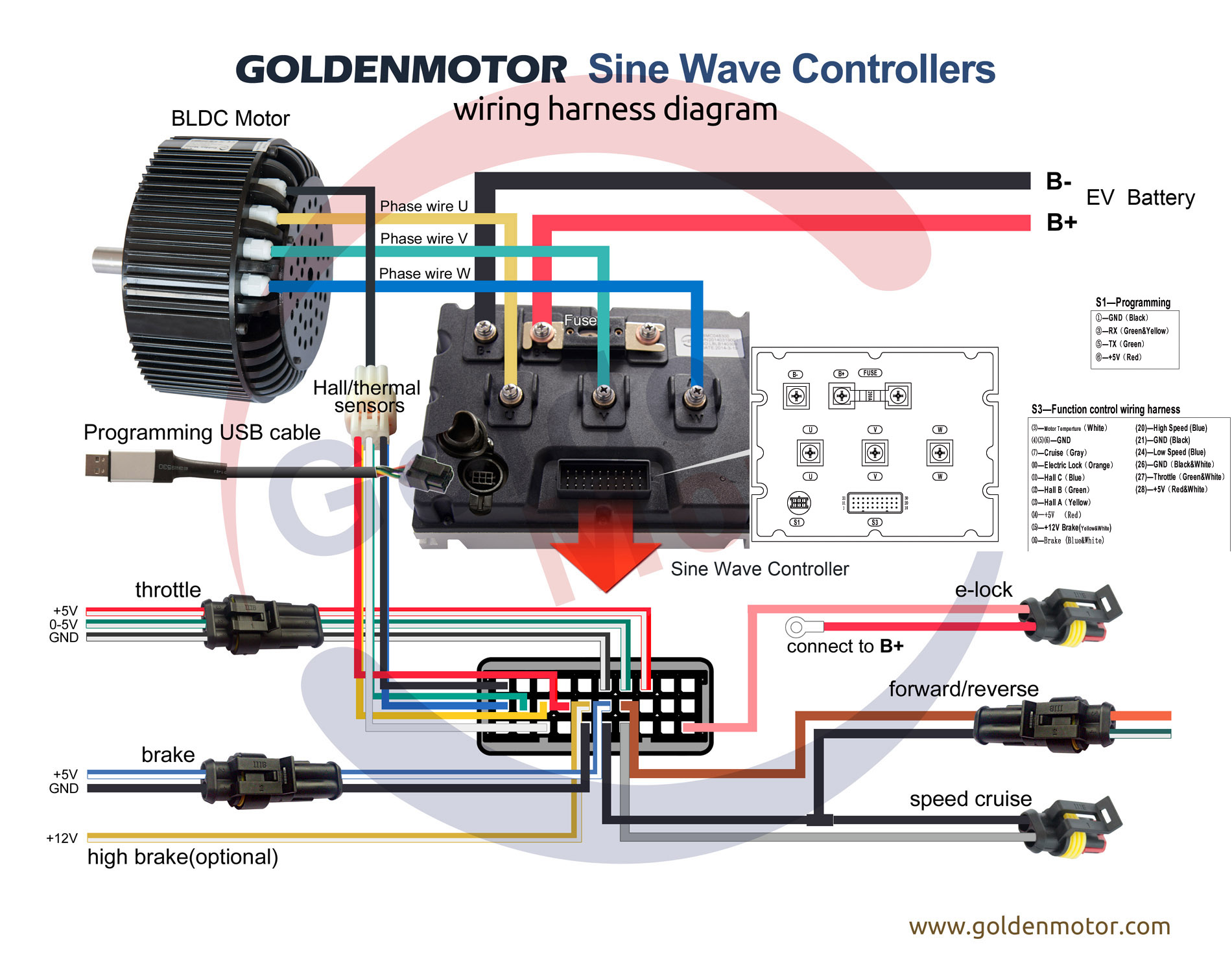
Seeing that the throttle control consisted of a ground wire, a 5V wire, and a 0-5V wire, I boldly assumed that the controller is expected to be a potentiometer, and went out and bought a slider.
Once I hooked it up however, I learned that the controller could be either a potentiometer, or a Hall effect sensor, and that the factory default setting on the controller was to expect the Hall effect sensor. Fortunately this was easily remedied by getting the programming cable for the controller, hooking it up to a computer, and changing the appropriate setting.
The second mistake was to just grab whatever slider was available at the electronics store, with the longest travel length shorter than the distance the throttle control cable could be moved by the control lever in the cockpit. The slider I ended up grabbing had a plastic tab that broke off under fairly ordinary use. I had a spare, so I dropped it in, and it broke too. There was enough of a nub left for me to be able to manipulate it directly until I could replace it properly.
With a bit of timing slack, I started looking around for heavier-duty sliders, found a family of relatively rugged sliders intended for mixer boards and ordered a pair (again, so there’d be a spare, even though I don’t expect this one to fail). Unfortunately, the most appropriate slider I could find in stock when I ordered was a PTF45-152B-503B2, though it would’ve been easier to fabricate a cable connector for it if the middle cluster (which describes slider tab shape and number of gangs) were 151A or 201A instead of 152B. That said, it’s a fairly minor detail, and easily worked with.
To start making the necessary mechanical connections, I obtained an electrical box and a blank faceplace for it. I then drilled holes in it for the slider’s mounting screws to pass through (and got some suitably sized machine screws to make that attachment) and milled a slot to accommodate the slider tab. The box and faceplate were then painted to match the motor (and reduce opportunities for corrosion).
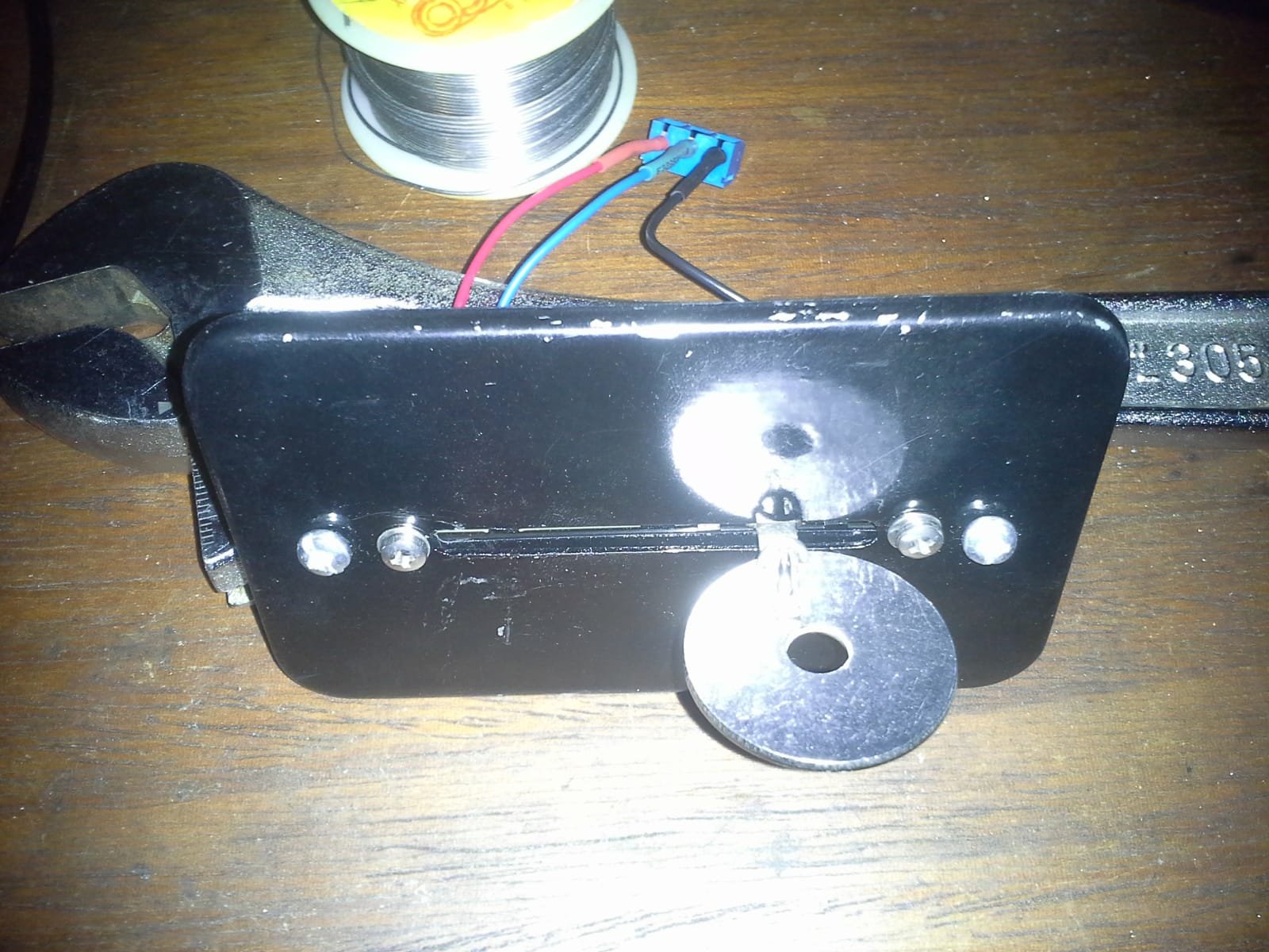
Since the end of the throttle control cable (to the lever in the cockpit) had a 3/16″ threaded protrusion with 2 nuts on it, sticking out from the end of the cable, the mechanical connection was achieved by taking a 3/16″ stainless fender washer, drilling a hole through it and the tab, passing stainless locking wire through that hole and bending the ends along the tab. This was then further secured by drilling a pair of holes in the washer, aligned with the concave sections of the tab profile, and forming a loop of wire through those holes, over both ends of the first wire, and twisted shut.
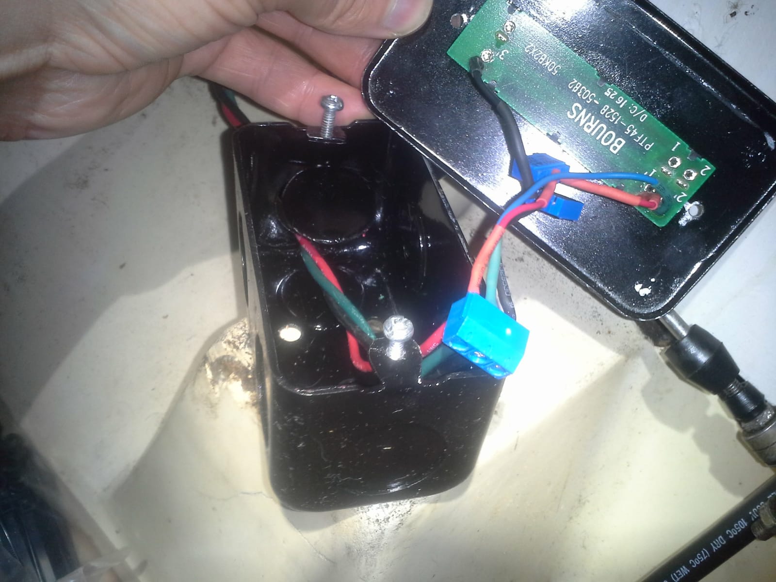
The resulting slider/faceplate assembly looks like this:
On the other end of the potentiometer, I soldered some wire to connect it to a screw terminal block, where the wiring back to the motor controller could be connected, and put a pair of trimmer potentiometers in-line on the 5V and GND lines to reduce the amount of slider travel that doesn’t affect throttle (as the controller doesn’t use the full 0-5V range). Only the bottom end has since been tuned, as I haven’t brought myself to run the motor at full throttle for long enough to tune the top end.
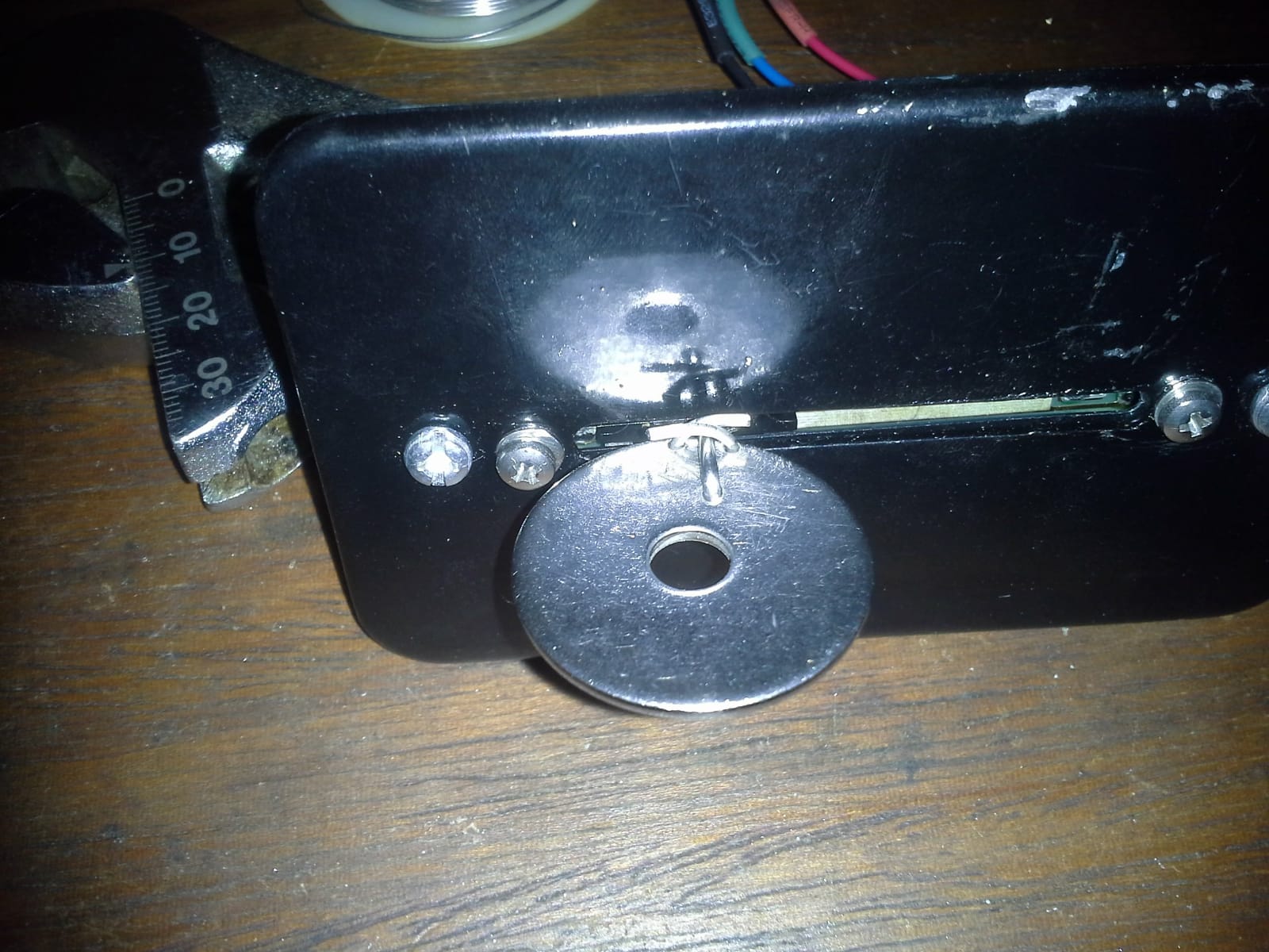
In this soldering job, I was caught by one other subtle unexpected behaviour in my parts. If you look carefully at the backside of the slider (in this image of its completed state):
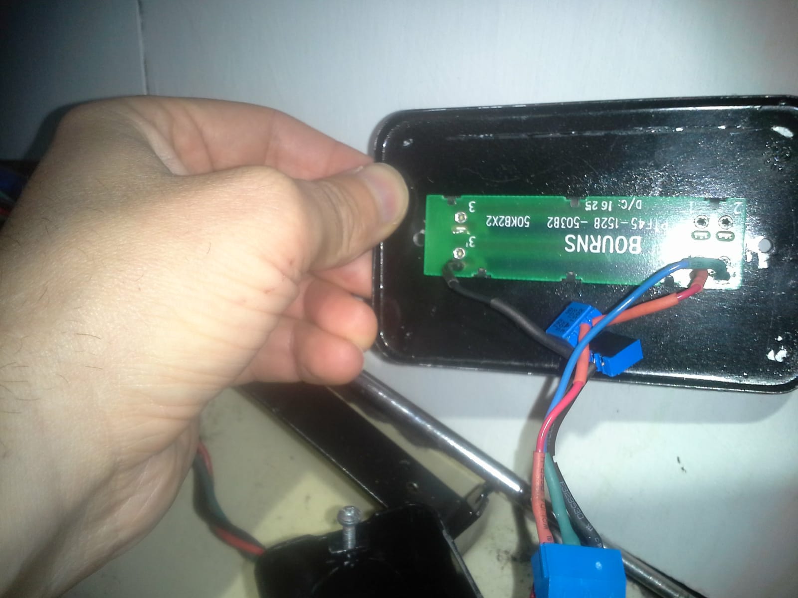
you may notice that the order of the pins is 2 1 3, not 1 2 3, as one might expect. Not only did I fail to check the pin ordering before soldering, but I decided to swap sliders on the day before the GLAA championships. Consequently, when motoring out of my slip, to head over to the hosting club that evening, the motor malfunctioned, I didn’t get anywhere, and ended up missing the race. For bonus points, the controller responded to this miswired slider by dropping some settings from its memory in a way that either a bug in the firmware, or a bug in the programming software, made it tricky to set back to the correct value (to tell the controller that 0V was no power, 5V was full power, and the direction controlled by the direction switch — instead of 0V being full power in one direction, 5V being full power in the other direction, and no power lying somewhere in the middle, the potentiometer vs. Hall effect sensor setting on the throttle had to be set to Hall effect sensor and left that way, in spite of the control being a potentiometer; it took a couple of weeks of debugging to figure this one out).
That said, once the controller was back in working order, all the wiring was reconnected, retested, and ready for work on the mechanical connections.
While the mechanical connection between the cable and the slider has been described, the stop for the cable housing has not. On the original Atomic 4, there was a notched tab on the side of the motor, which a slot in the end of the cable housing could fit into, and another notched tab a few inches away, to help stabilize the cable. To imitate this, I took a strip of 16ga sheet, milled notches into the ends, and then bent those ends up by 90 degrees (I was even all proper about it and used a brake, insted of pliers and a vise). I then drilled a pair of holes on either side of the notch (so the cable housing could be tied or wired in place for extra security, even though it fits snugly), and painted it to match the control box and motor frame.
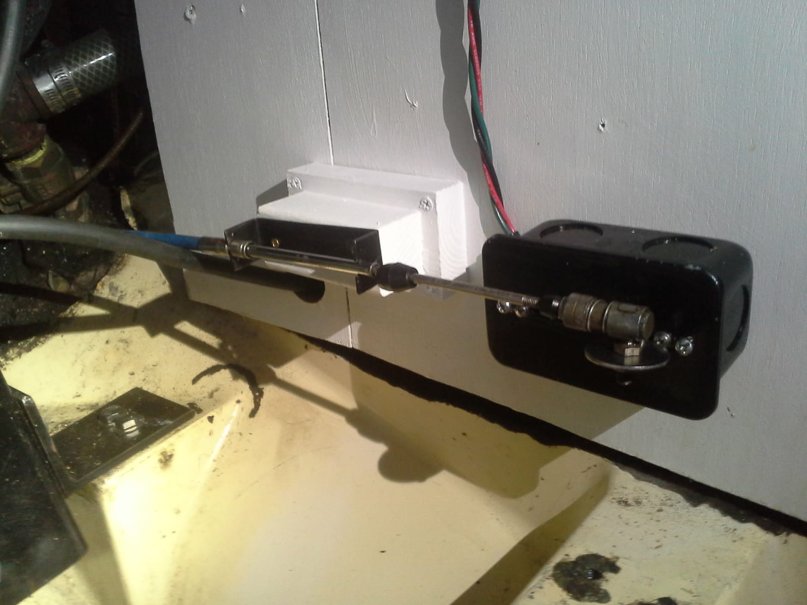
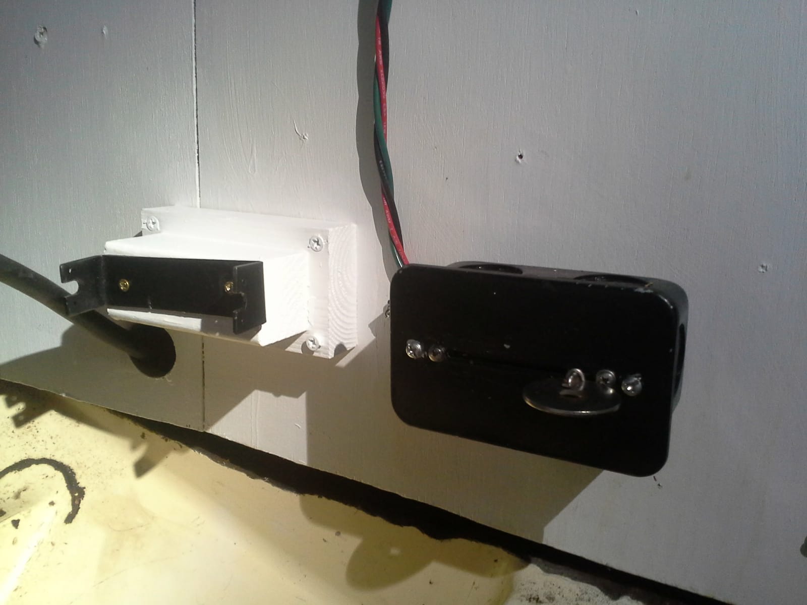
However, the lengths of the bent up notches was chosen for rigidity/stability, not for keeping the cable housing a distance from the side of the engine compartment that matched the distance from said same slide to where the cable end would mate with the slider. This however was easily fixed with a wooden block, screwed to the side of the engine compartment, where the stop might otherwise go, and then painted to match the compartment:
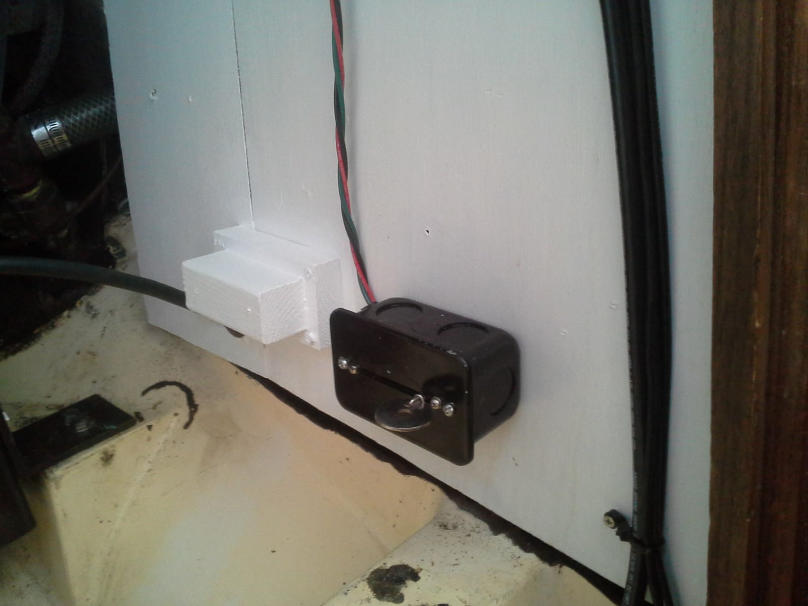
Then the housing stop was installed:
And all that remained was to connect the control cable: