
Building an electric motor for Candy Cane, part 3: Assembly and installation
Although I trusted my measurements (and machining) enough to have cleaned and painted the frame before test-fitting any of the associated components (which also were on the boat, rather than in the machine shop), once the frame was on the boat, it seemed like that had gone on for long enough.
First I tested the fit of the motor (since that’s really what bit me on the prototype):
and then seeing that it fit, made sure that everything else did too:
Once that was figured out, I slid in the transfer shaft, grabbed the flanges (which I’d spared from the prototype), and stacked things under the frame until the transfer shaft and prop shaft were aligned (to the point that I couldn’t get a 0.001″ feeler gauge in between the butted shafts from any angle, and a straightedge run along the shafts, across the junction, with a light shining behind it, didn’t show light peeking through any steps from one to the other (at 3 or 4 different positions on the shaft — I can’t remember exactly, as I’m writing this nearly a year later). With the frame properly in place, I put the flanges next to it (on the engine mounts), and marked the centres of their holes for drilling mounting holes into the frame. It’s worth noting that the new frame was 2″ wider than the old frame, so I had to trim the back corner off of one of the flanges with a hacksaw before it would fit — however this also meant that I didn’t have to line the new frame up with the old bolt holes in the mounts.
The frame was then removed, the bolt holes drilled and tapped, and the exercise repeated, but with the flanges getting bolted to the frame, instead of having the location of their mounting holes marked. (All of this alignment was enough of a bother that if I were to repeat this project, I’d also design mounts that simplify alignment.) Once the flanges were secured to the proper alignment, assembly could begin. This would start with the transfer shaft.
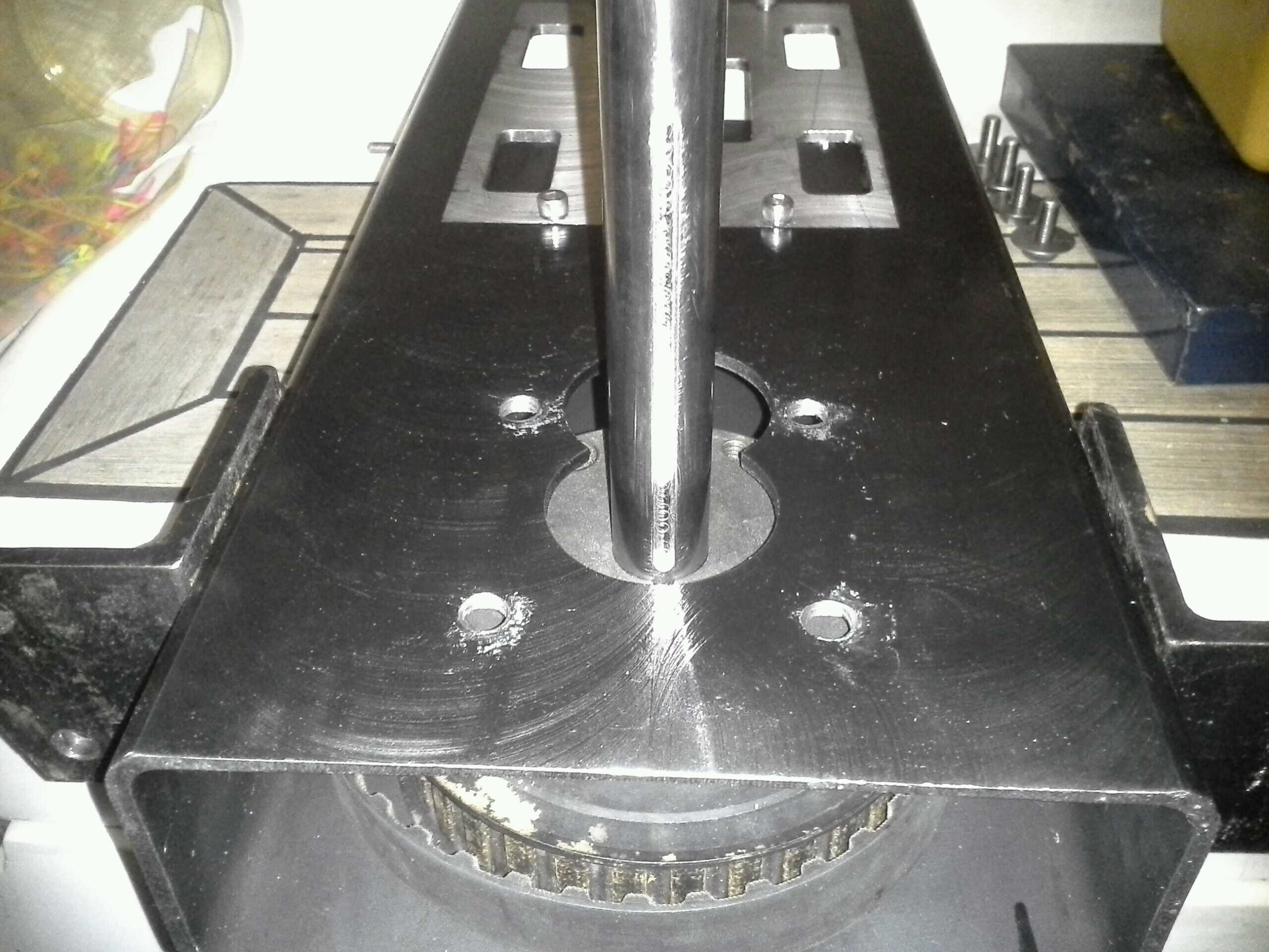
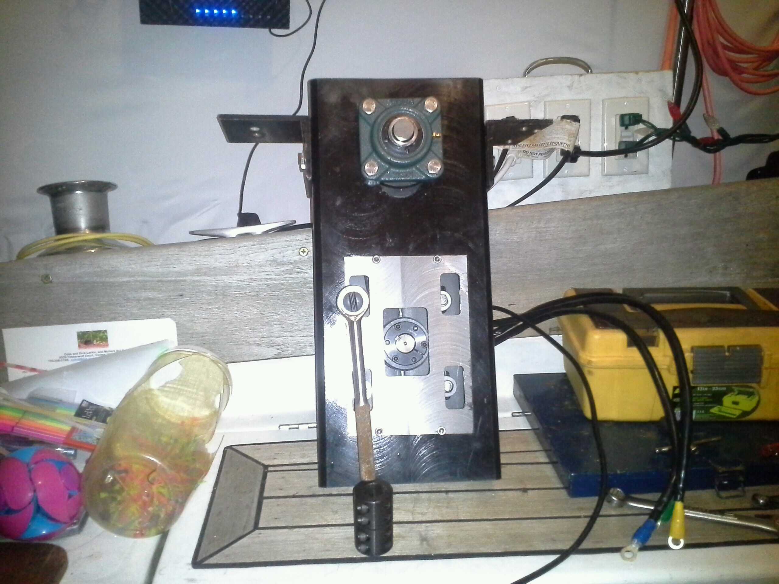
Since the transfer shaft is secured in bearings at both the forward and aft faces of the frame, and it has to pass through the belt (and its pulley), it had to be removed, and these parts put in place for the shaft to pass through them. Additionally, the forward bearing needed to be removed, in order to provide access to the tightening screws on the pulley’s split taper bushing. Thus the frame prepared for the shaft looked like this:
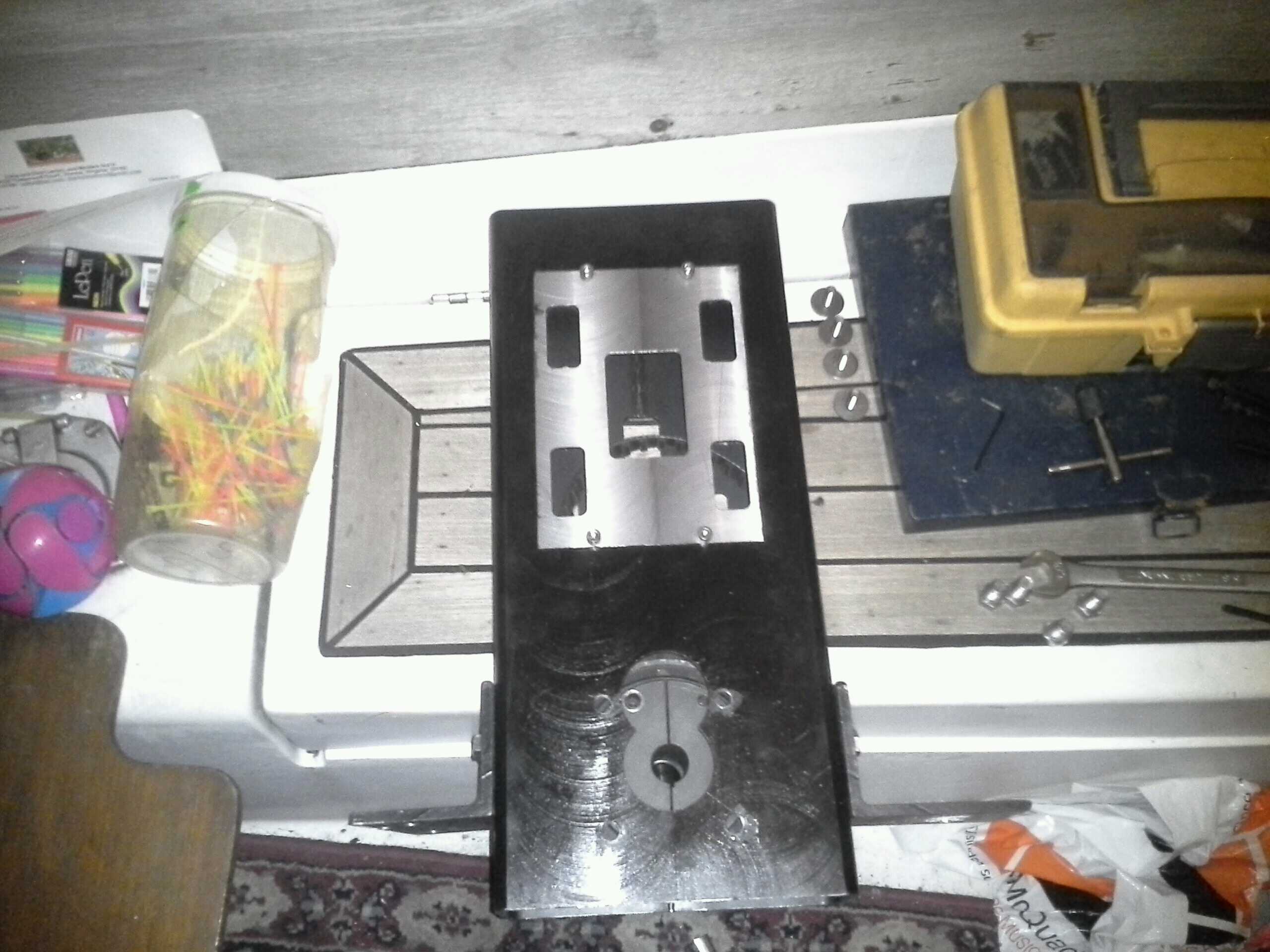
At this point the shaft could be partially inserted, just enough to line its keyway up with the keyway on the bushing:
This allowed the machine key to be put into the shaft’s keyway, and then slid into the pulley to provide that form of coupling as the shaft was slid far enough through the whole assembly until its stickout behind the aft end of the aft bearing was measured to be the same as when the alignment was done. At this point the set screws on the aft bearing were tightened to secure the shaft at this distance, small spacers (just pieces of scrap I had laying around) placed under the pulley to ensure it’d clear the inside aft face of the frame, and the bushing screws tightened down to secure the pulley in place on the shaft. The spacers were then removed and the motor pulley slipped inside the belt:
The bearing was then slid on, bolted into place, and the set screws removed, and the positions of their holes marked in the shaft with a small grinder. The bearing was then unbolted and slid back off; the grinder was once again applied to the shaft to enlarge the marking dimples and allow the set screws to reach the softer steel beneath the case-hardening (to prevent the shaft from sliding fore or aft in the frame under thrust loads. This is totally the wrong way to do this, and I should have used thrust bearings instead. That said, this is what’s there and it seems to be working reliably out on the water, in varied conditions).
The bearing was then replaced and bolted down, and the shaft spun in the collar until the dimples lined up with the holes for the set screws, and the set screws put in.
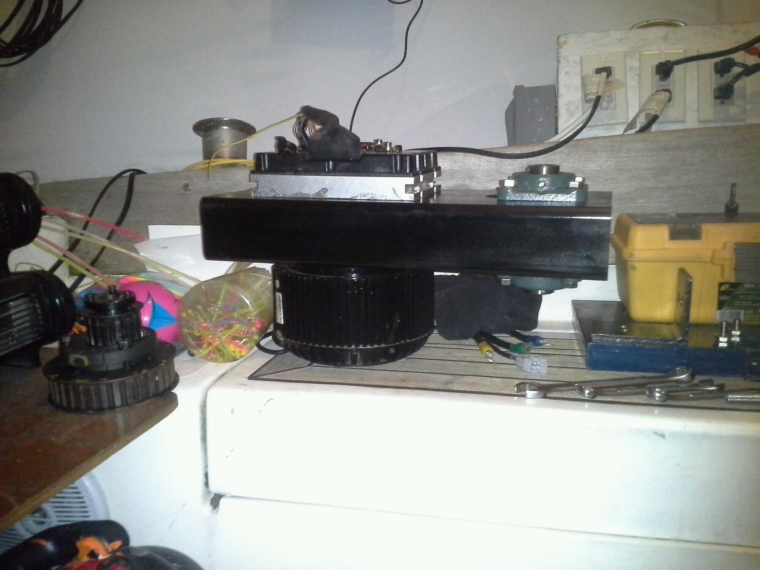
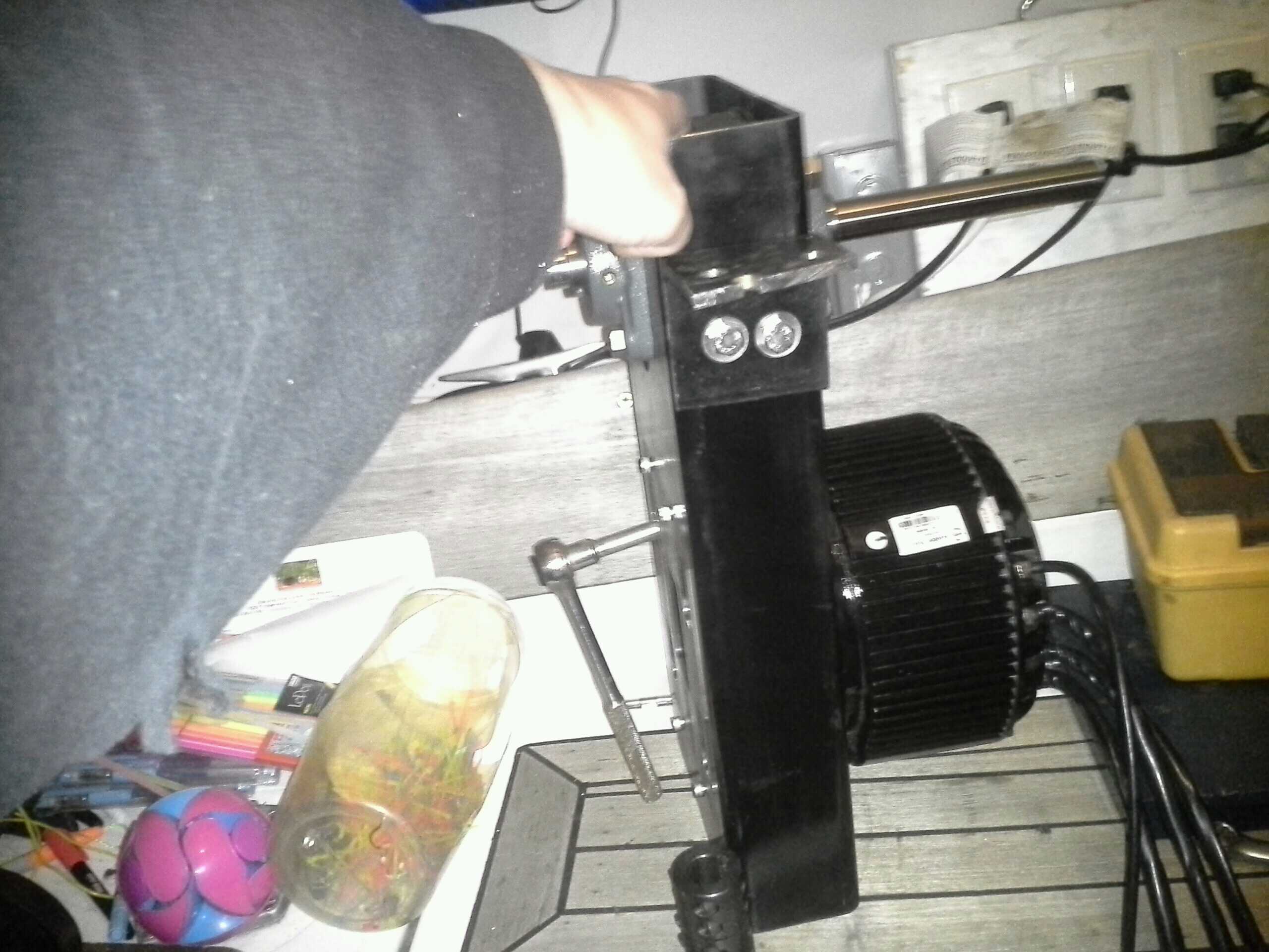
The frame was then placed on the motor, with the motor’s shaft passing through its pulley; the key was put in the bushing’s keyway, and the bushing slid onto the motor shaft and into the taper on the pulley). The motor was then loosely bolted to the frame and this picture taken:
The motor’s bolts were then tightened into the frame just loosely enough to still be able to slide the motor on the frame. The frame was then rested on its end, motor side down, and the motor allowed to slide down and tension the belt with its weight, like this:
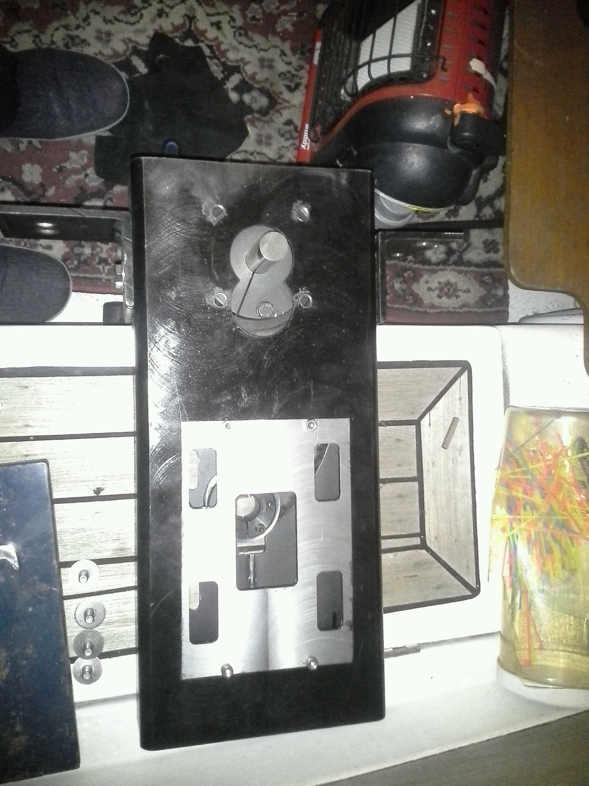
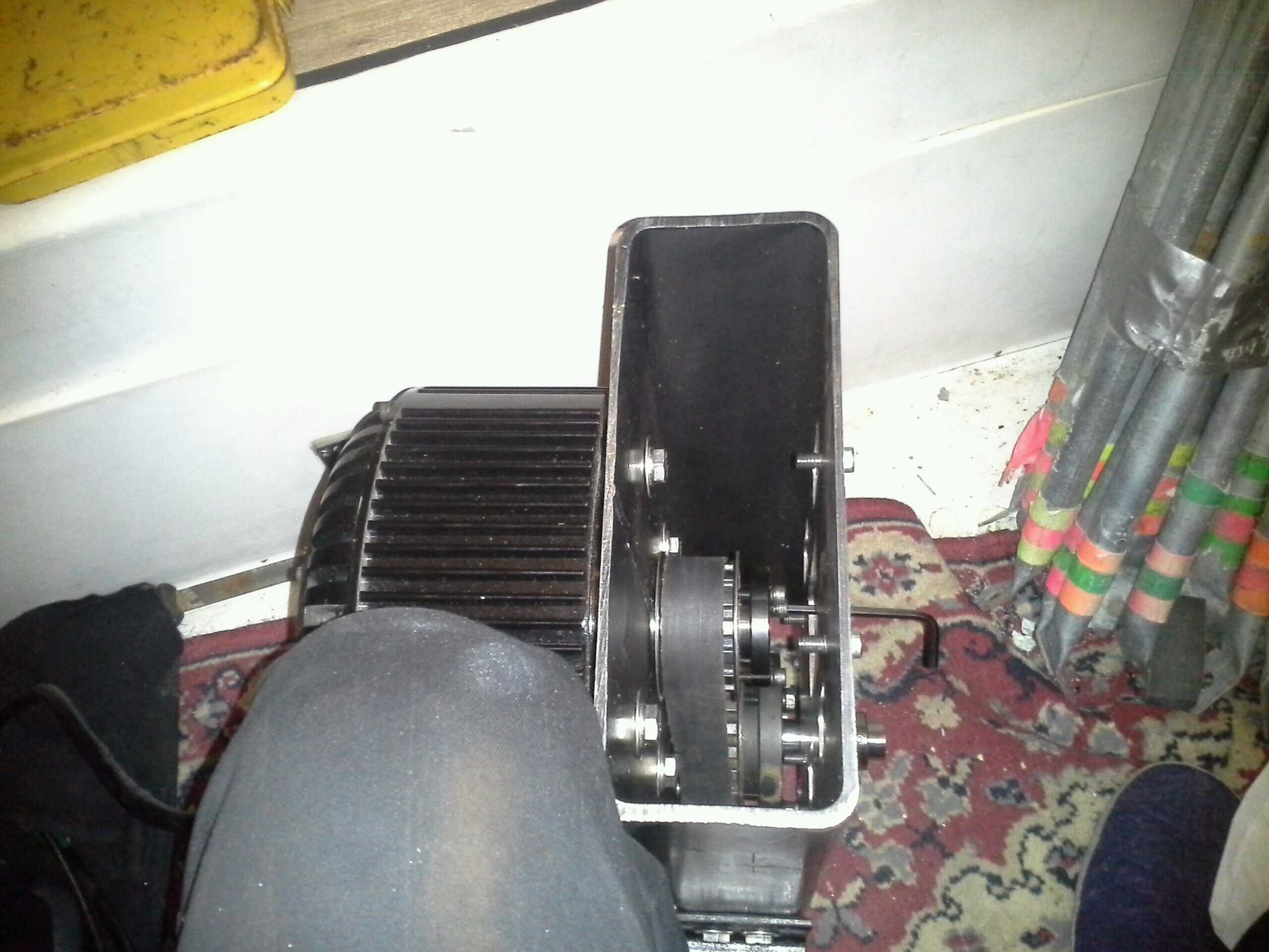
The bolts were tightened to secure the motor in place, by inserting the socket wrench through the access holes as shown in these pictures (taken after the motor was already tightened on); one taken of the front:
and another of the side:
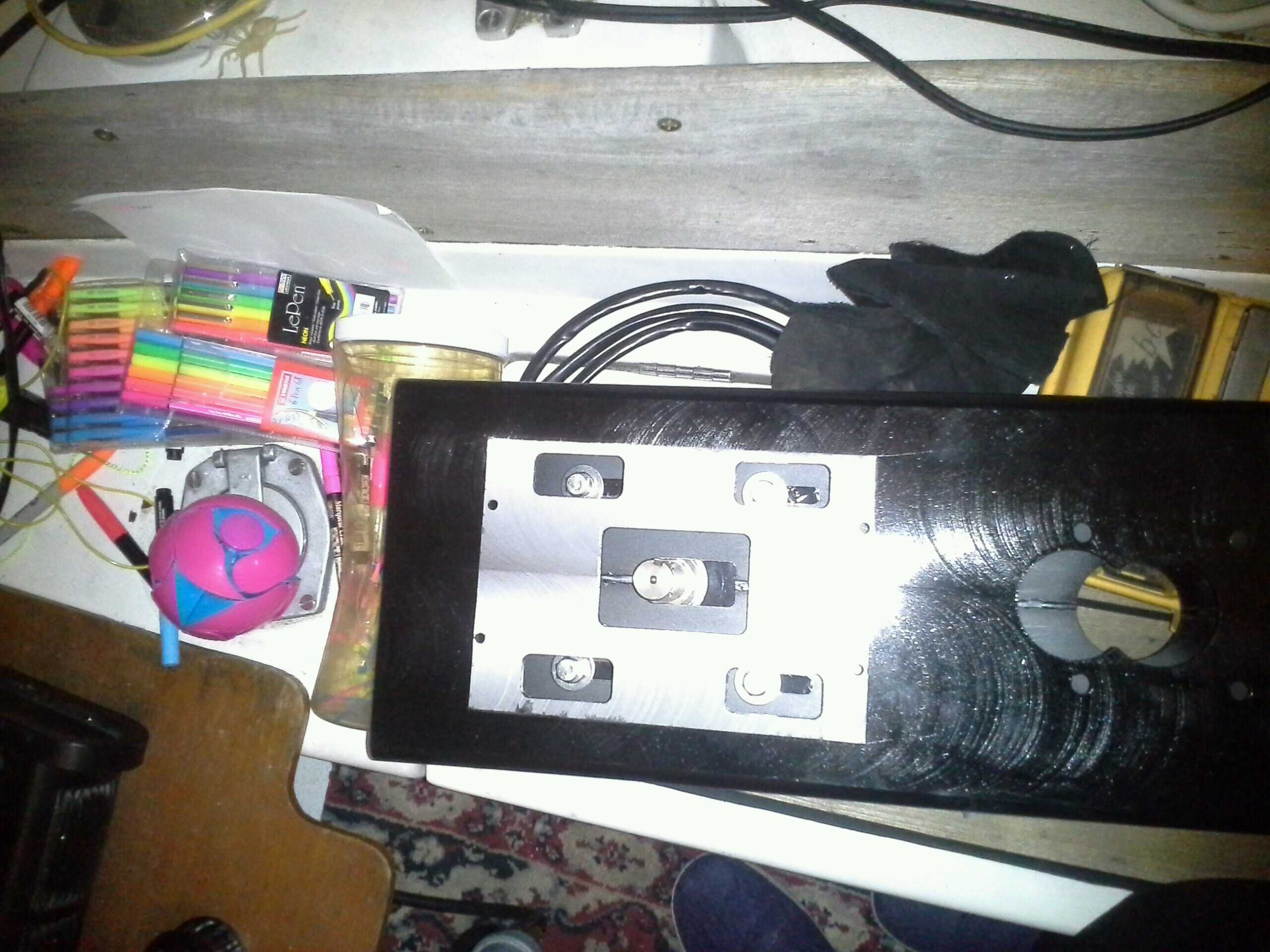
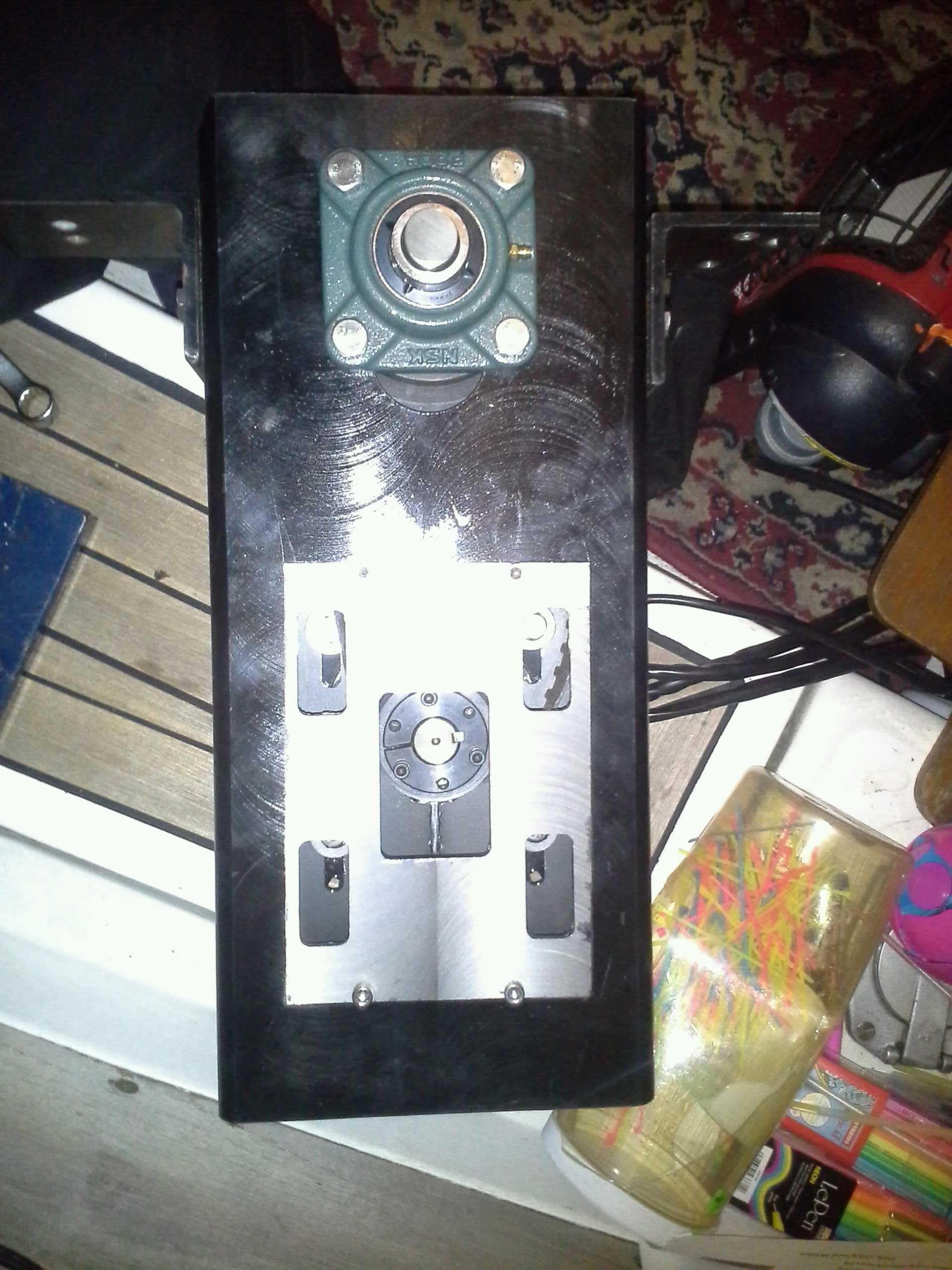
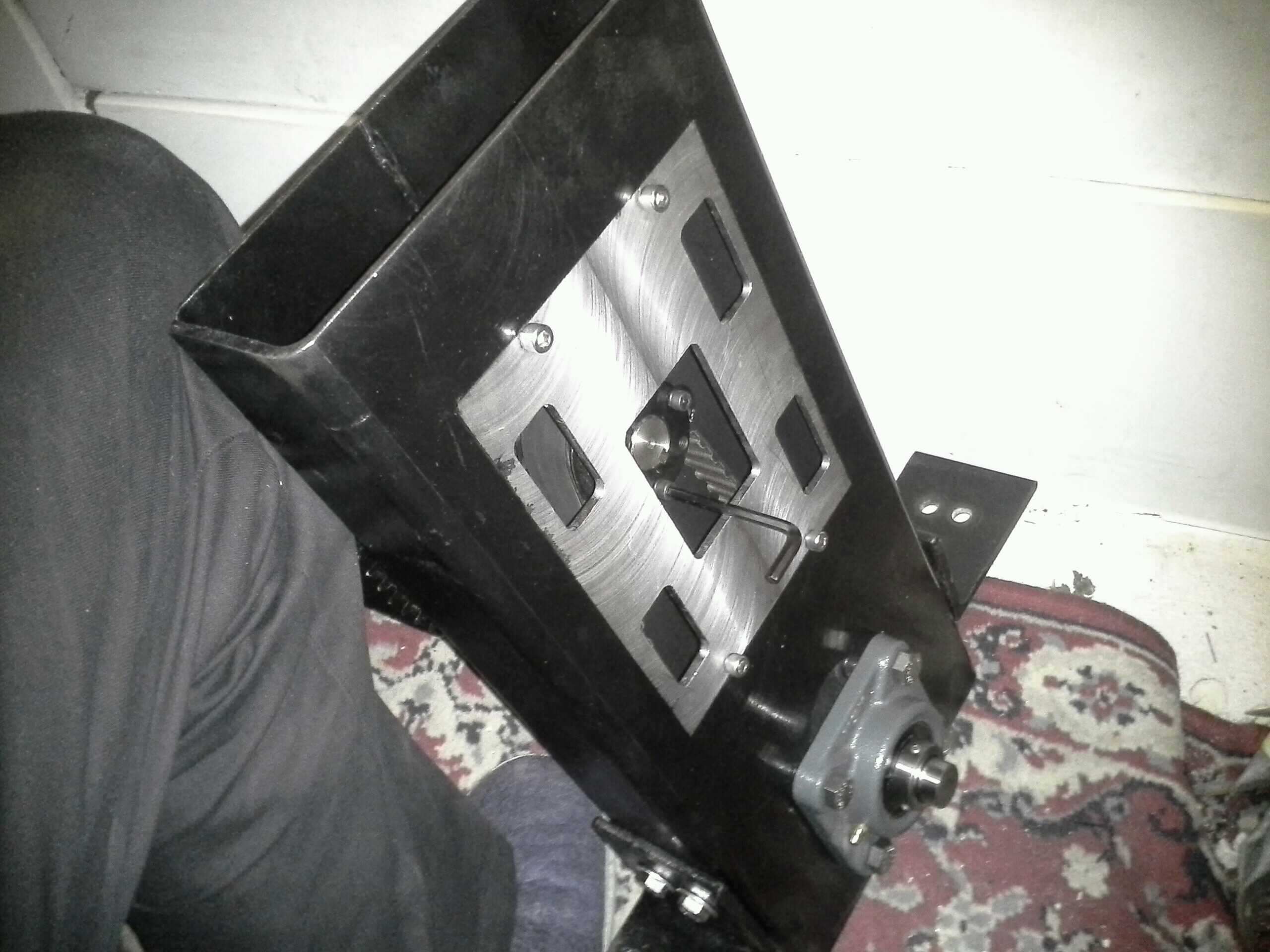
At this point, the motor pulley was nudged along the shaft into a position that both cleared the aft wall of the frame, and lined up properly with the belt as fed over the transfer pulley. The bushing screws were then tightened with an allen key through the access port as shown below; from above:
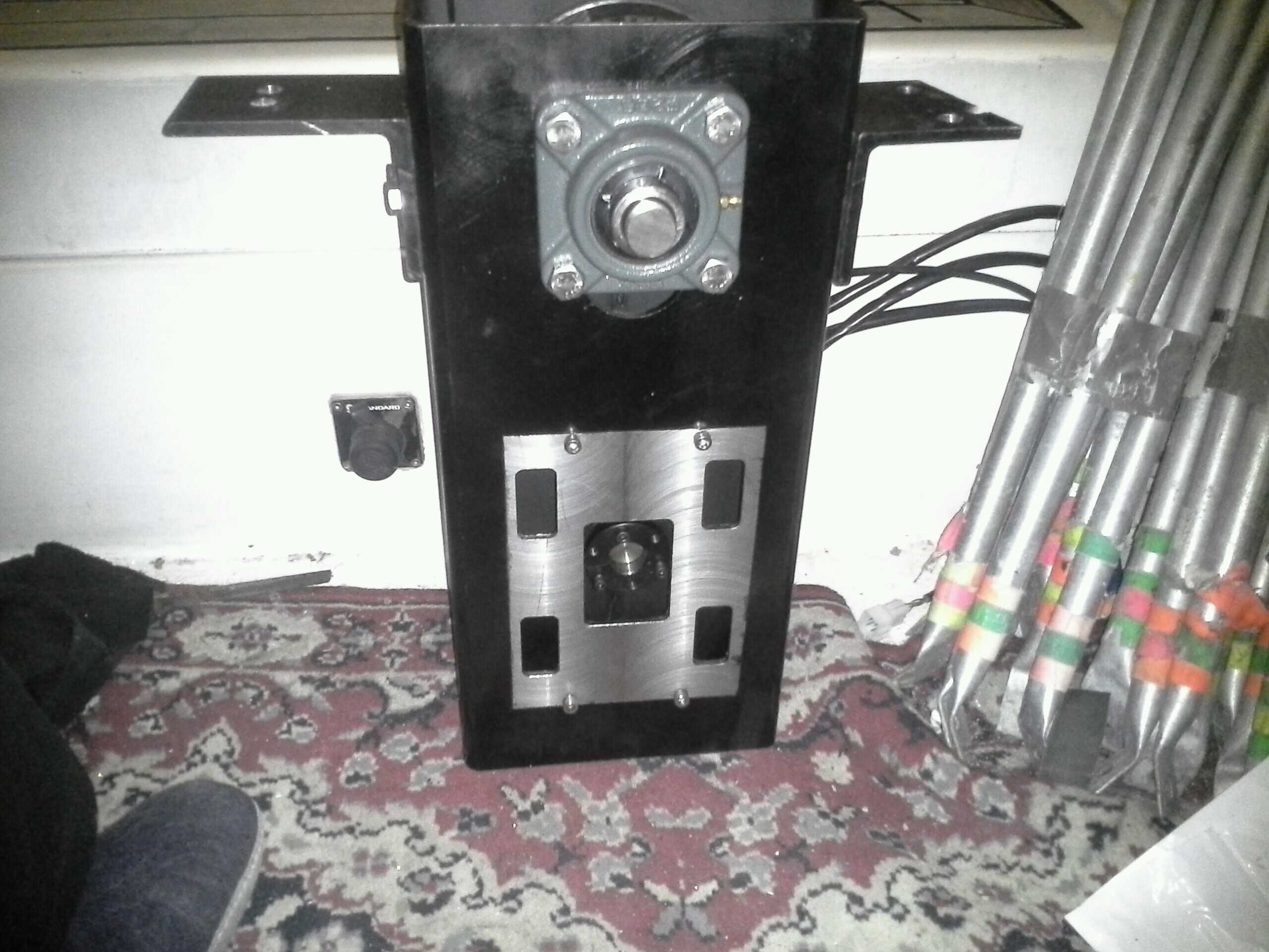
and from the front:
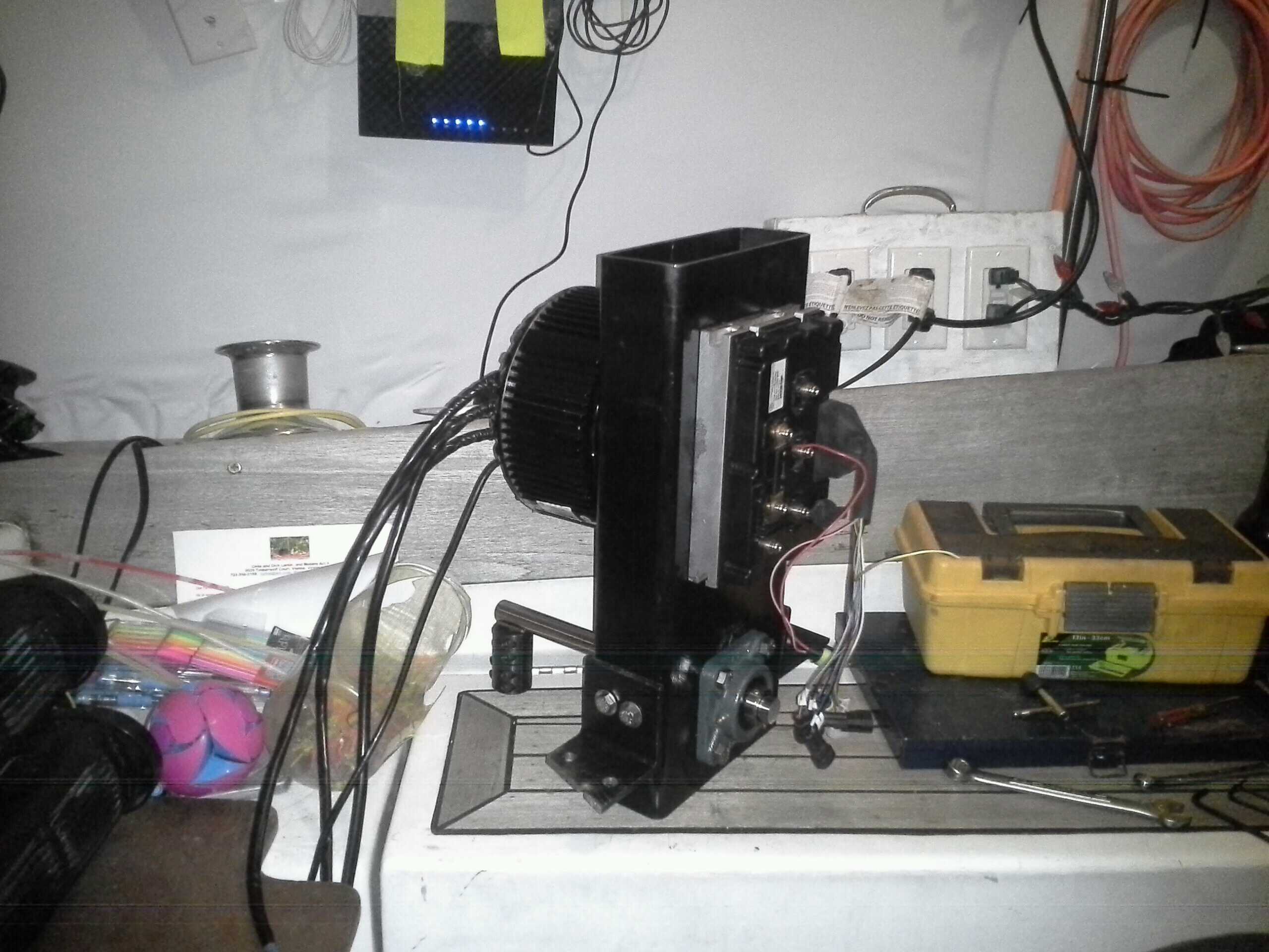
At this point, the mechanicals are done, and the controller can be bolted to the fore face (after applying some copper anti-seize), yielding a nearly completed motor:
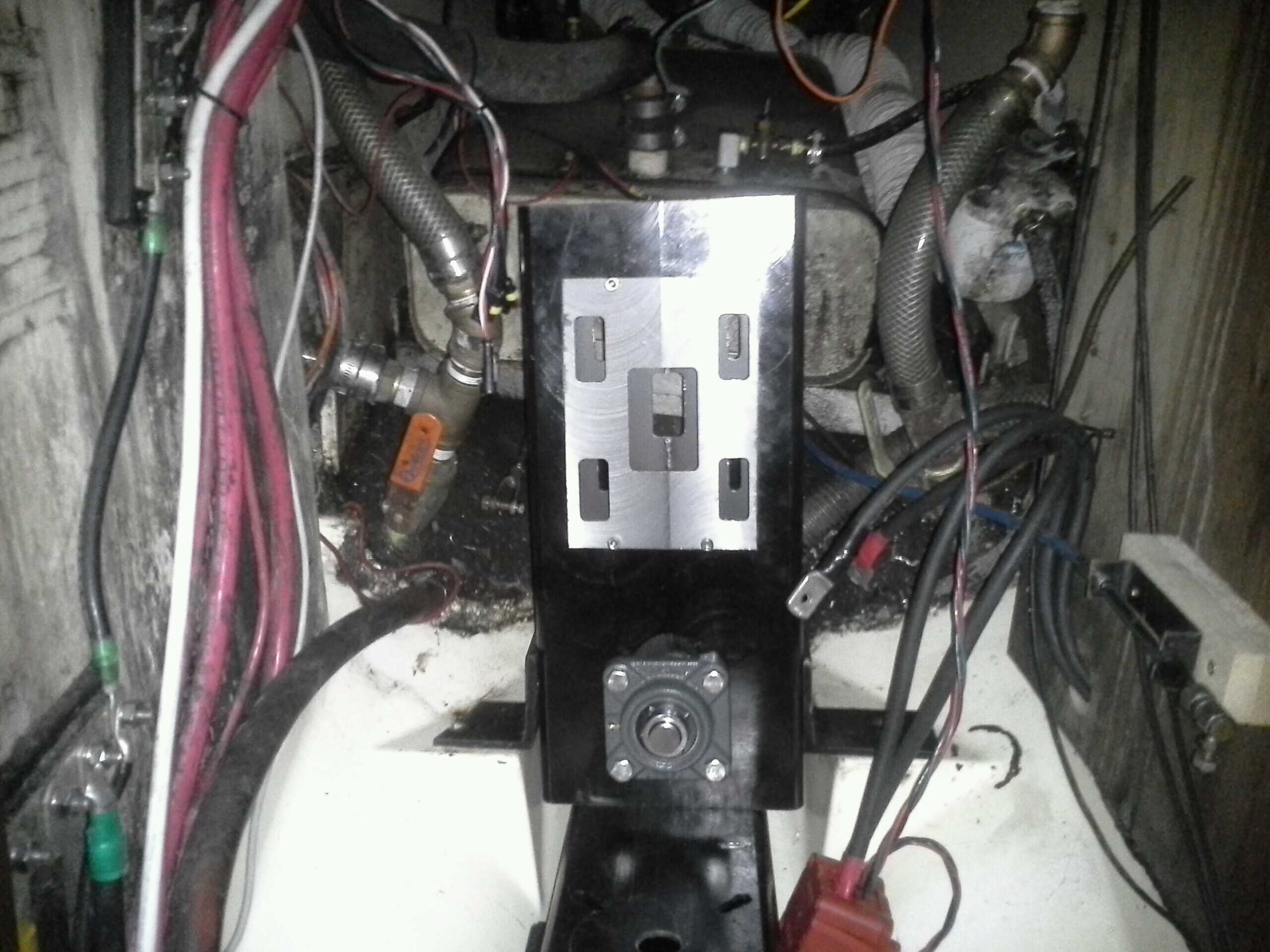
The motor was then connected to the controller, installed (with yet more alignment), and then connected to its power lines from the battery.
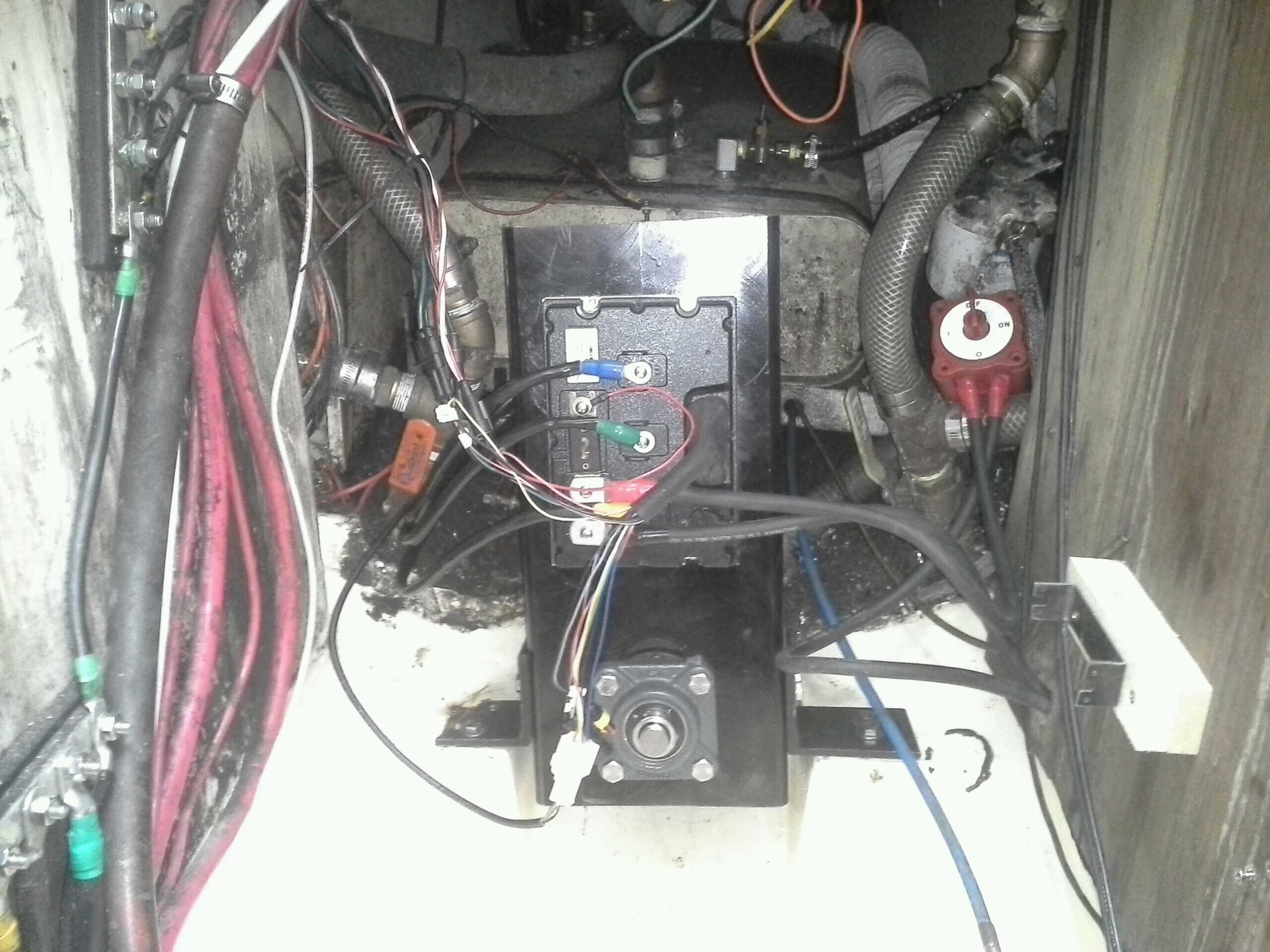
This leaves only the controls to be connected, which is the subject of another post.