
Building an electric motor for Candy Cane, part 2: Machining a new frame
So because of the space constraints inside the old frame (and also because availability of suitably sized pieces of metal is sometimes a factor in what I build with), I opted to make the new frame out of 3×8″ rectangular tubing with a 3/16″ wall (instead of the 3×6″ — same wall thickness — that the old frame had been made out of). Even if I’d stuck with the smaller box, the new frame would still have started with a reminder of why I was reluctant to start over until the old frame was truly unworkable: facing is a slow and tedious operation.
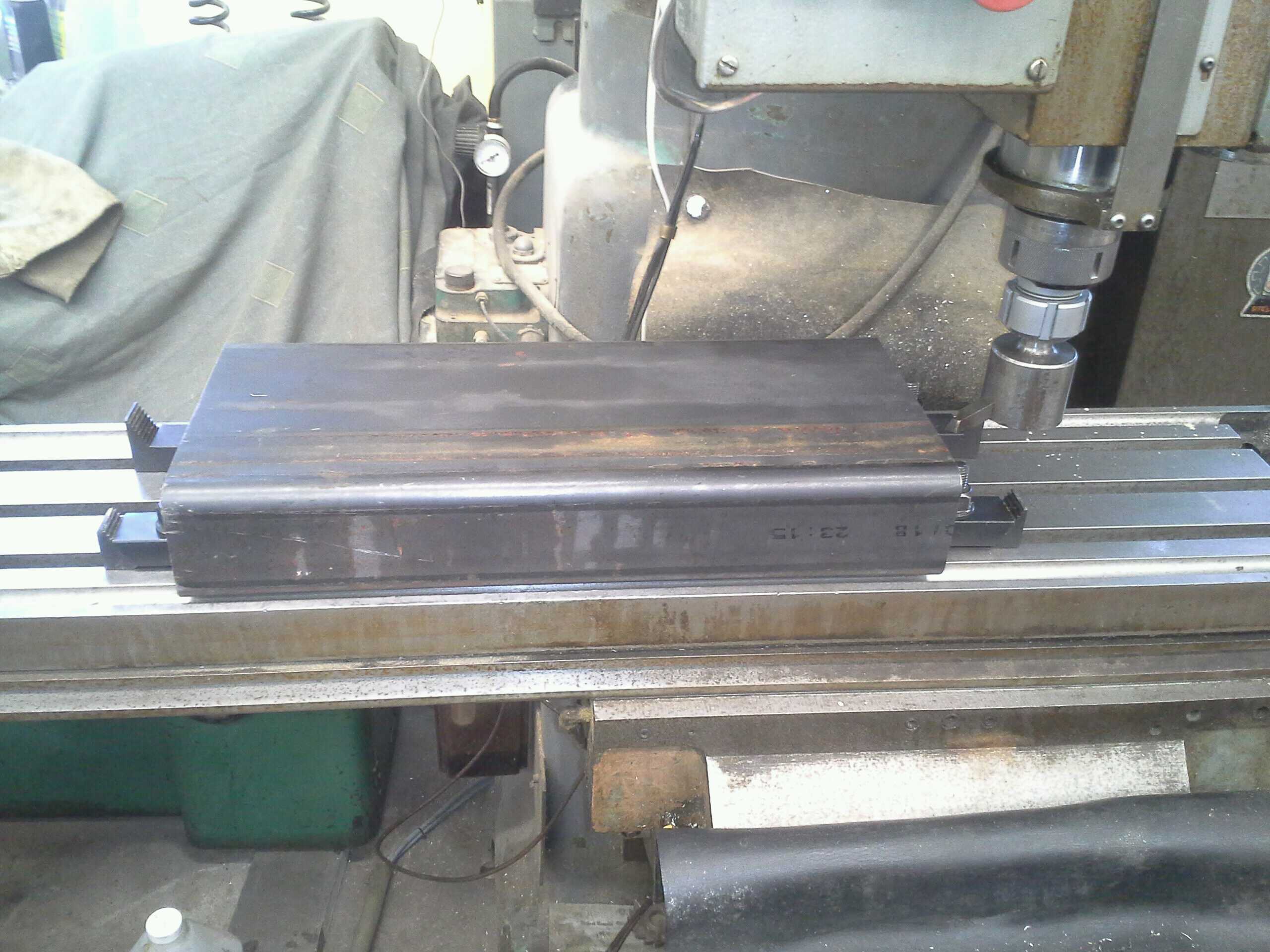
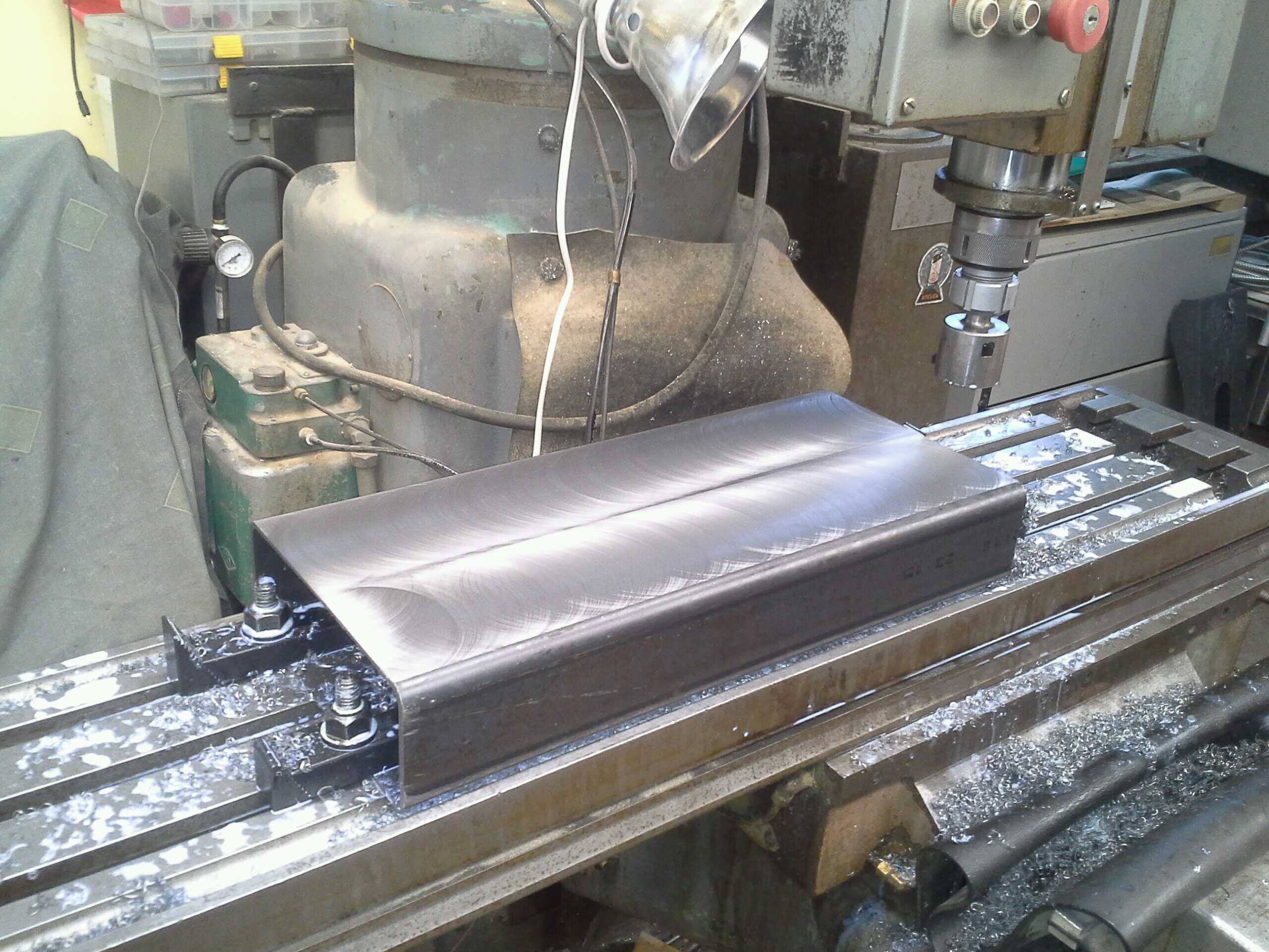
A fresh piece of rectangular tubing like this:

needs to be shimmed on the first side (so it won’t bend when clamped or rock on the table when it’s being machined), loosely aligned (I was facing with a fly cutter that had an effective diameter just large enough to cover the face of the tube in 2 passes — but only if the workpiece was reasonably well-aligned) and clamped down.
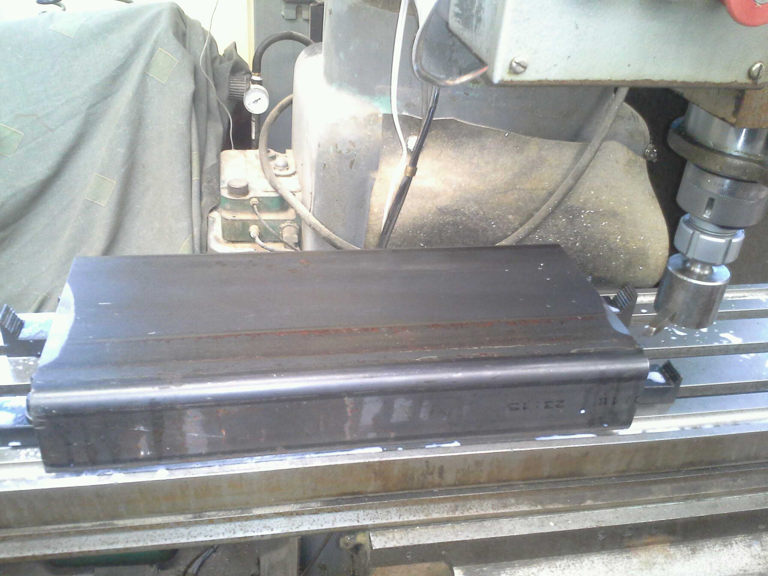
Because I didn’t want to take off too much material, it was necessary (at least once the cutting was starting to get going) to take more shallow cuts, rather than fewer deep cuts. I knew how much shimming the workpiece had required (about 0.045″ on both sides), and had zeroed the Z-axis on the machine to the middle of an end of the tube (which is normally where high points occur), and taken a fairly high-speed (manual) pass at a depth where I didn’t expect any cutting to occur, just to make sure I had indeed zeroed to a high point. And then I still only lowered the tool something like 0.020″ on my first pass (because I’m a masochist with time to waste):
Pretty early on, I figured out that I should run the the mill manually at the proper feed rate (about 1.1″ per minute (ipm)) until it stopped cutting, then crank the speed up to about 30ipm, drive it forward until it started to cut, back it off to just before where it started to cut, and then finish the pass at the proper speed under CNC control (and do this for both directions).
Even with early, more aggressive cut depths, this was still a huge time-saver for a few passes:
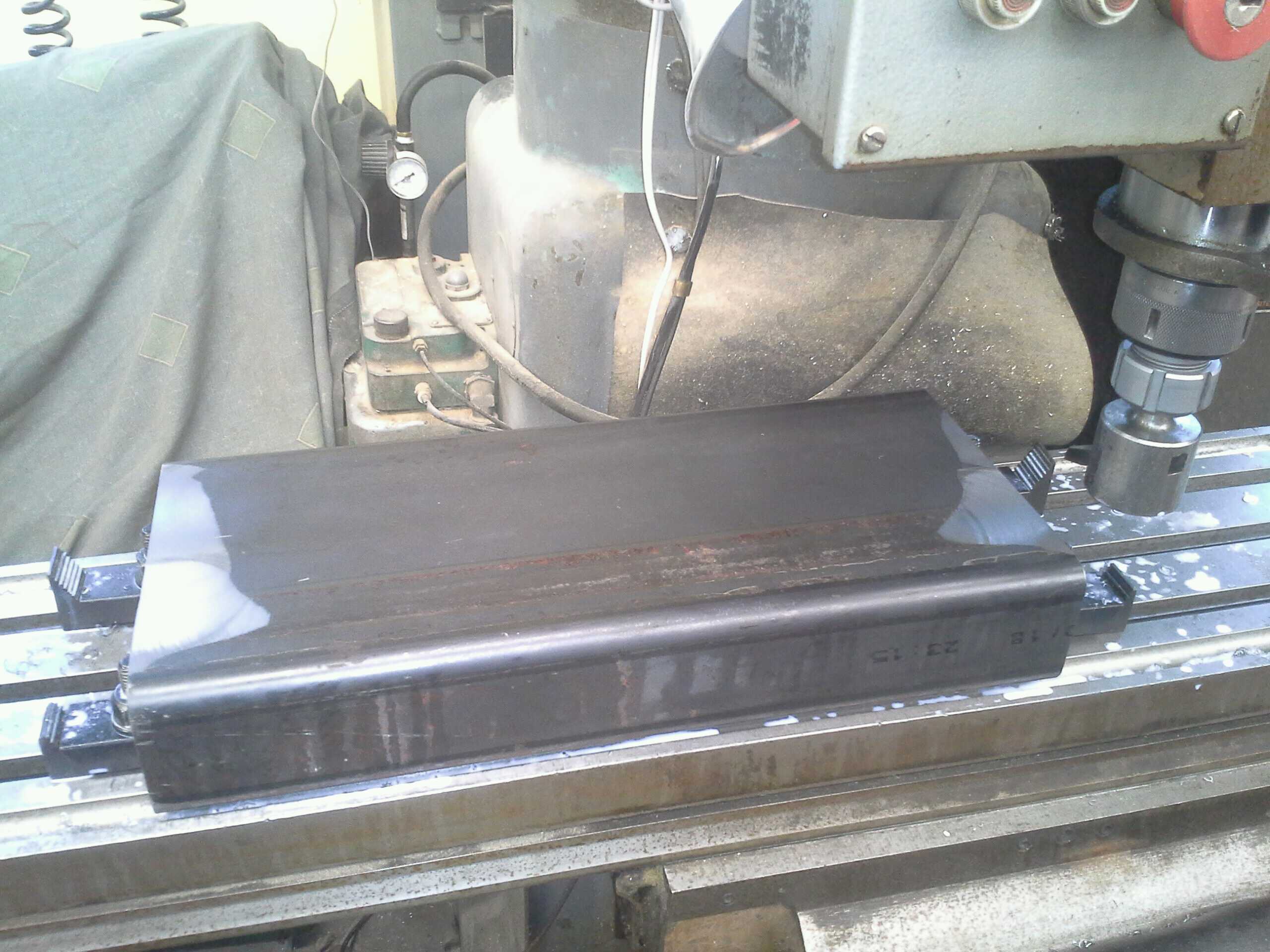
Though not for too many passes:
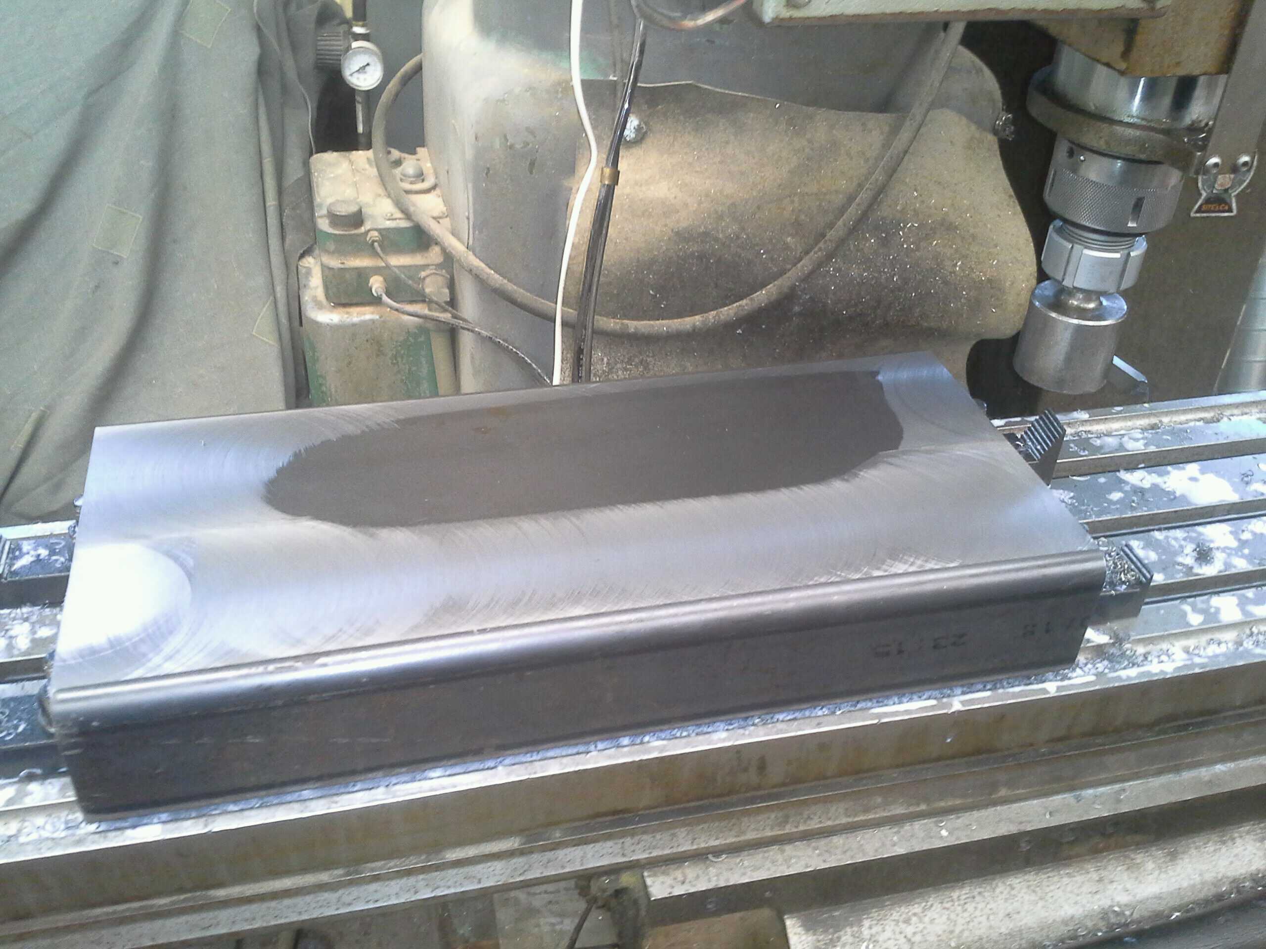
Eventually, I had a flat enough face to work with, and could flip the tube over and do it all over again (well without the shimming) to face the other side and have proper surfaces to mount hardware to:
Following this, I drilled in the bolt holes for the bearing flanges. Because I hadn’t yet figured out that I should move away from self-aligning bearings, I instead took great care to make sure that the bolt holes on the fore and aft faces lined up very precisely with each other, and used bolts presenting little enough slack that the proper hole placement could make sure the transfer shaft’s axis of rotation was square to the frame faces (and therefore also parallel to the motor shaft’s axis). If you’re making a similar project, don’t waste your time repeating my mistake; just use a flange mounted bearing with an axis of rotation square to the flange face by virtue of its construction (i.e. nearly any non-self-aligning flange bearing).
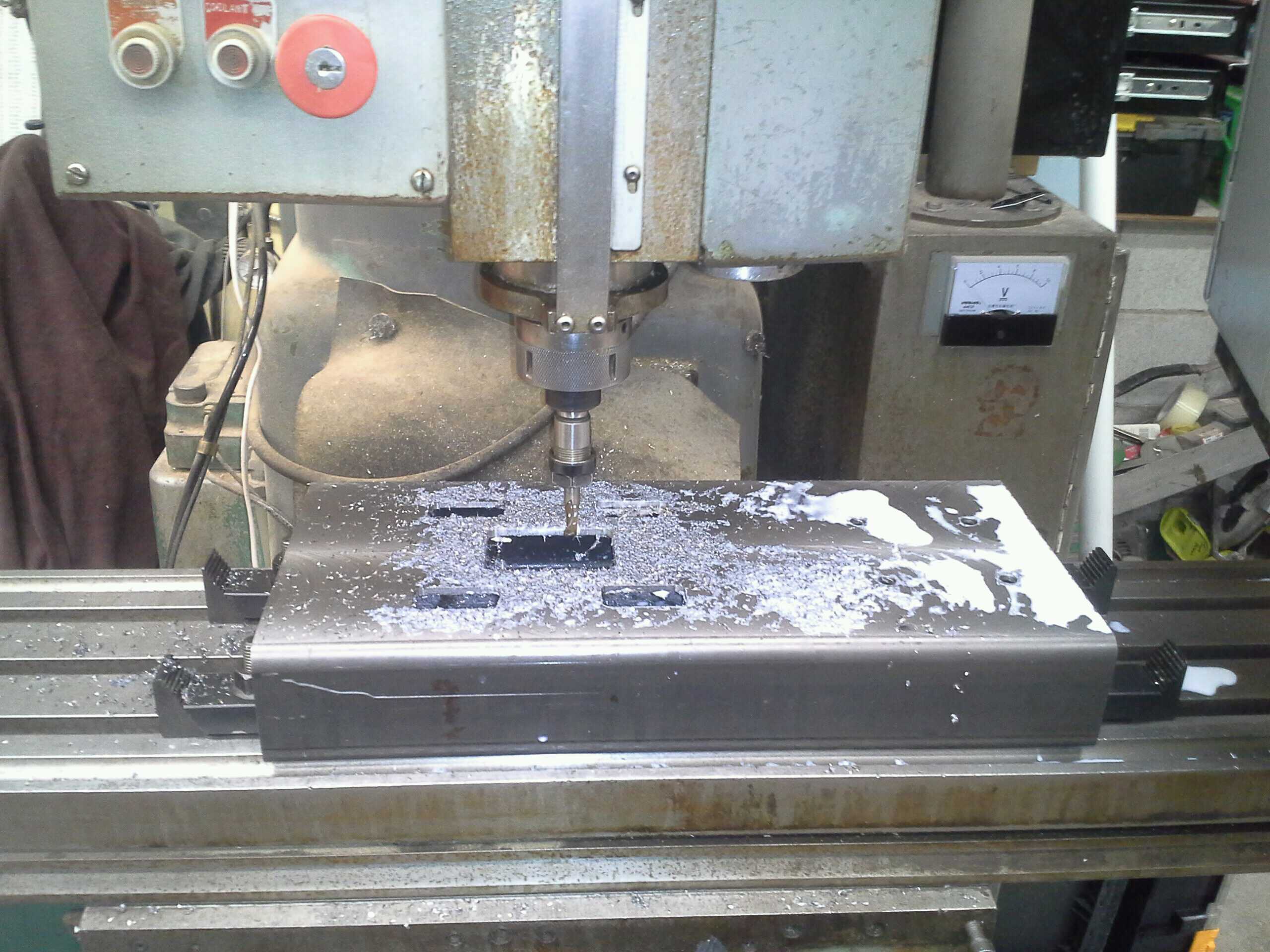
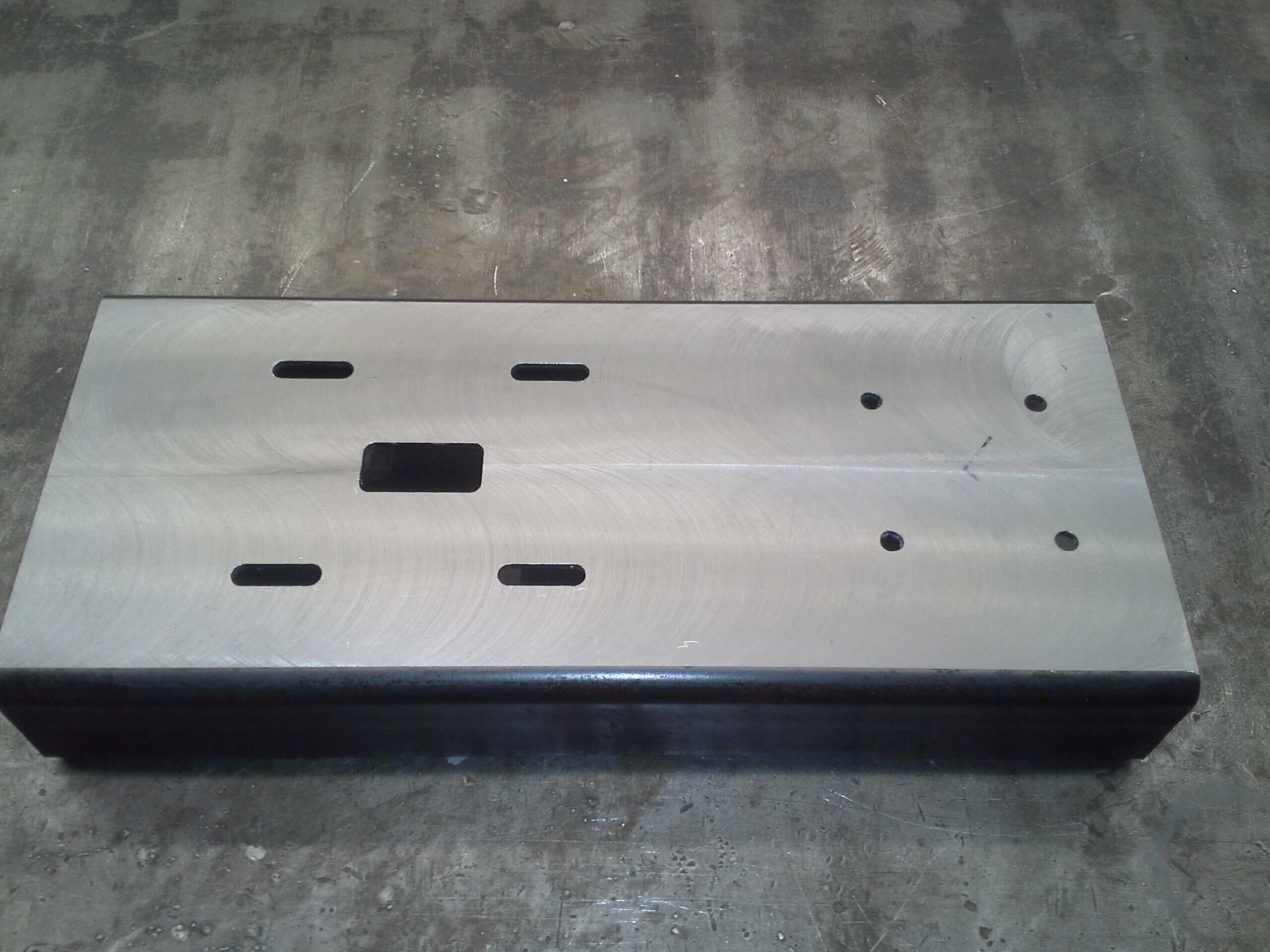
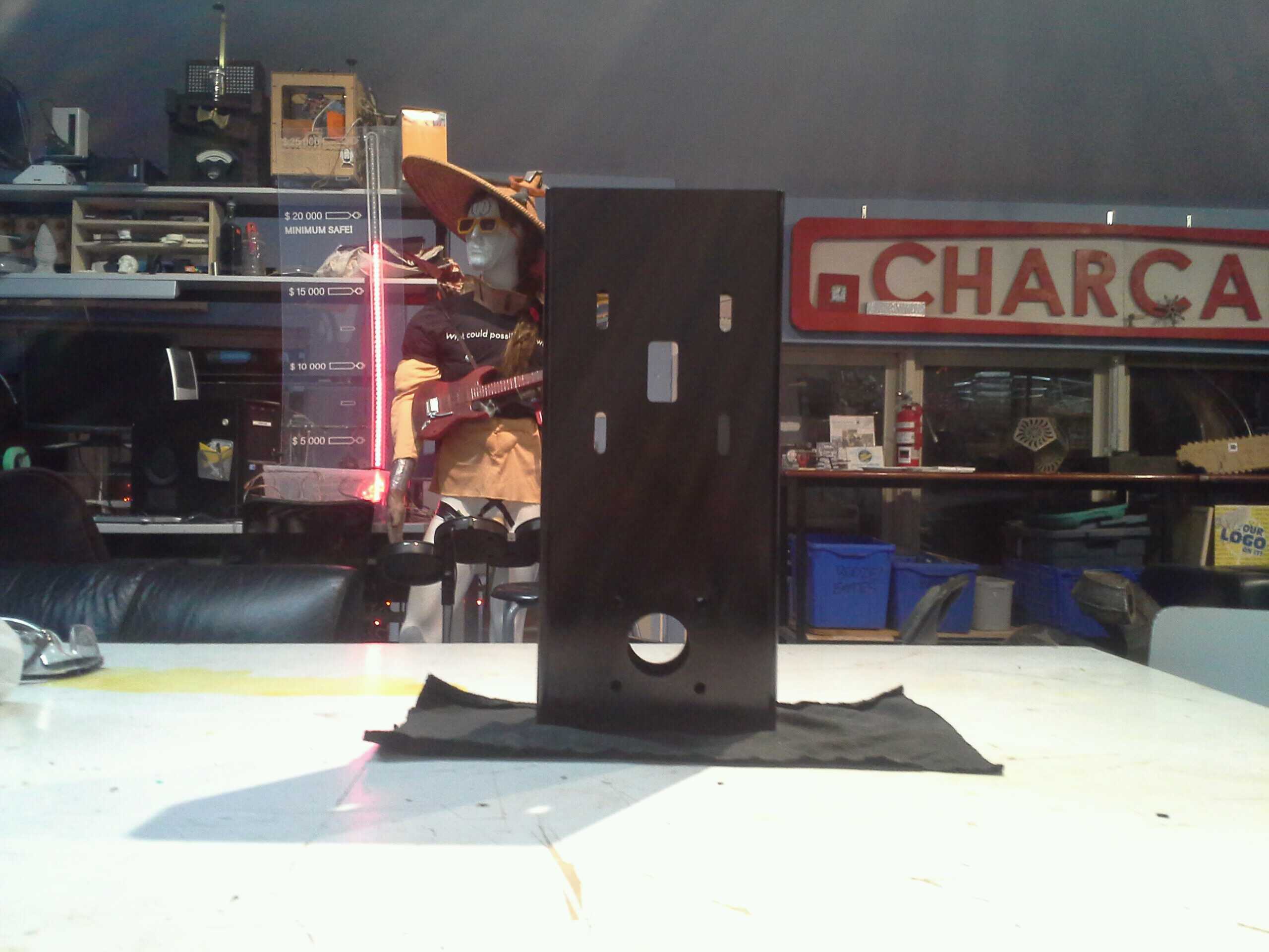
Once the bearing mounting holes were in place, I use them to scribe in where the motor shaft would go — on both sides of the frame. The reason for this is that I wanted to put access ports on the front of the frame, lining up with the bolt holes and the shaft, through which I could insert tools to tighten the bushing screws (the one lining up with the prop shaft), and to tighten down the motor bolts (through the other 4 holes). The bolt tightening holes became important because the motor would be secured with the belt under tension, which meant that the belt and pulley would get in the way of using open-ended wrenches for the bottom two bolts (also being able to spin a socket wrench around without having to worry about its handle hitting the sides of the frame). So I milled rectangular holes into the front face: the hole over the motor shaft was about as wide as the motor pulley (in what would be the horizontal direction, once mounted), and since the bolts for the motor had 12mm head, the hole over the bolt holes was about 1/2″ wider than the outside of my long 12mm socket. To allow for adjustment, of motor position, all the holes were 1″ taller than they were wide (the centre position for these holes corresponded to the distance between shafts that would reasonably closely fit the 30″ belt I already had from my previous version, so I could get maximum adjustment in both directions). In the end, this yielded a front face that looked like this:
I then repeated the operation for the aft face, except that instead of the width of the centre hole being around the width of the pulley, it was 1″(for a 7/8″ shaft, to allow some clearance), and the width on the bolt holes was approximately the nominal size of the bolts. Again, all the holes were an inch longer than they were wide:
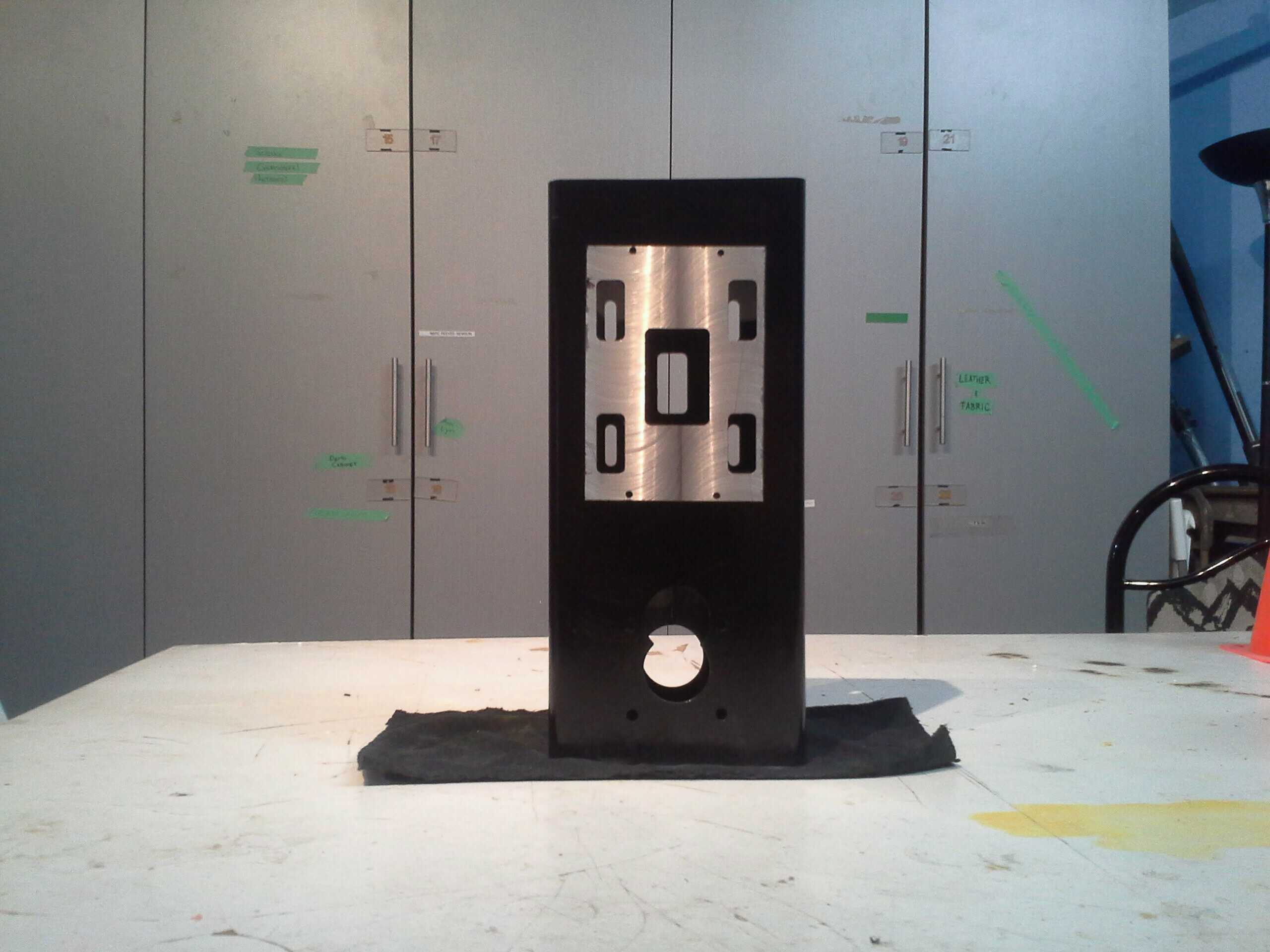
After cleaning up, you can see the fore face, and the slots of the aft face through it:
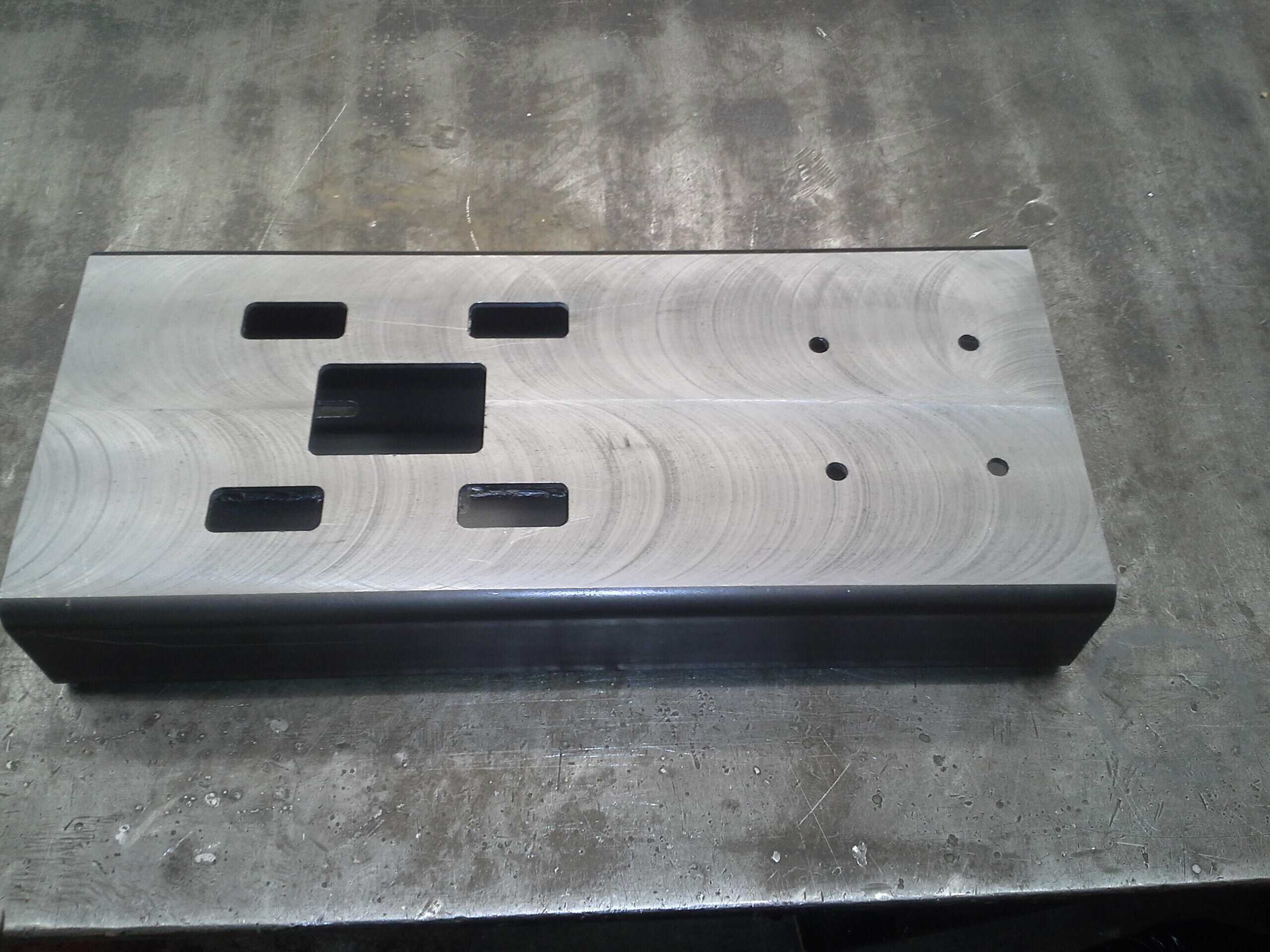
This done, I then took a hole saw (one larger than I needed, but it was what I had handy) and used it to cut holes for the transfer shaft (oversized enough that alow clearance for a seated 3/16″ key in a keyway in the shaft) at the centre point between the bearing bolt holes. On the forward face I cut an additional hole about an inch higher to ensure I could access the bushing screws once the bearing was removed (unfortunately, I couldn’t guarantee this without having the hole move past where the bearing flange would cover it up, so there’s a bit of opening in the forward face of the fully-assembled motor.
I also placed the controller over the access holes on the front face, and used that position first to place holes for the screws to mount the controller to the frame. Then after degreasing the fully machined frame, I applied masking tape around where I expected the edges of the controller to go, screwed in the controller, and used a knife to cut the masking tape along the edges of the controller. Removing the surplus tape, I was then able to fill in the rest of the space where the controller would go with more tape, and paint the frame (liberally because it’s made of steel and going on a boat). I felt it was important to keep the metal bare under the controller because the controlled looked very much like it was designed to use the machinery it was mounted to as a bit of a heat sink, and I’d be applying a thermally conductive anti-seize compound when doing its final installation. Here’s what the frame looked like with the frame applied (i.e. basically finished):
And at this point, it’s all ready to be built back into a motor and installed in the boat.